AD7878SQ Analog Devices Inc, AD7878SQ Datasheet - Page 11
AD7878SQ
Manufacturer Part Number
AD7878SQ
Description
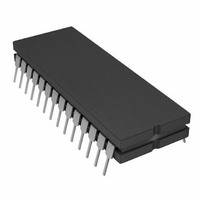
IC ADC 12BIT W/DSP INT 28-CDIP
Manufacturer
Analog Devices Inc
Datasheet
1.AD7878JPZ-REEL.pdf
(16 pages)
Specifications of AD7878SQ
Rohs Status
RoHS non-compliant
Number Of Bits
12
Sampling Rate (per Second)
100k
Data Interface
DSP
Number Of Converters
1
Power Dissipation (max)
95.5mW
Voltage Supply Source
Analog and Digital, Dual ±
Operating Temperature
-55°C ~ 125°C
Mounting Type
Through Hole
Package / Case
28-CDIP (0.600", 15.24mm)
Available stocks
Company
Part Number
Manufacturer
Quantity
Price

Part Number:
AD7878SQ
Manufacturer:
ADI/亚德诺
Quantity:
20 000


Positive Full-Scale Adjust
Apply a voltage of 2.9978 V (FS/2 – 3/2 LSBs) at V
until the ADC output code flickers between 0111 1111 1110
and 0111 1111 1111.
Negative Full-Scale Adjust
Apply a voltage of –2.9993 V (–FS/2 + 1/2 LSB) at V
just R2 until the ADC output code flickers between 1000 0000
0000 and 1000 0000 0001.
MICROPROCESSOR INTERFACING
The AD7878 high speed bus timing allows direct interfacing to
DSP processors. Due to the complexity of the AD7878 internal
logic, only synchronous interfacing is allowed. This means that
the ADC clock must be the same as, or a derivative of, the pro-
cessor clock. Suitable processor interfaces are shown in Figures
18 to 21.
AD7878–ADSP-2100/TMS32010/TMS32020
All three interfaces use an external timer for conversion control,
allowing the ADC to sample the analog input asynchronously to
the microprocessor. The AD7878 ALFL output interrupts the
processor when the FIFO preprogrammed word count is
reached. The processor then reads the conversion results from
the AD7878 internal FIFO memory.
REV. A
Figure 17. AD7878 Full-Scale Adjust Circuit
Figure 18. AD7878–ADSP-2700 Interface
1
. Adjust R2
l
and ad-
–11–
The interfaces to the ADSP-2100 and the TMS32020 gate the
AD7878 CS and the BUSY to provide a signal which drives the
processor into a wait state if a read/write operation to the ADC
is attempted while the ADC track/hold amplifier is going from
the track to the hold mode. This avoids digital feedthrough to
the analog circuitry. The TMS32020 does not have separate
RD and WR outputs to drive the AD7878 DMWR and
DMRD inputs. These are generated from the processor STRB
and R/W outputs with the addition of some logic gates.
AD7878–M CC8000
This interface also uses an external timer for conversion control
as described for the previous three interfaces. It is discussed
separately because it needs extra logic due to the nature of its
interrupts. The MC68000 has eight levels of external interrupt.
When interrupting this processor one of these levels (0 to 7)
has to be encoded onto the IPL2–IPL0 inputs. This is achieved
with a 74148 encoder in Figure 21, (interrupt Level 1 is taken
for example purposes only). The MC68000 places this inter-
rupt level on address bits A3 to A1 at the start of the interrupt
service routine. Additional logic is used to decode this interrupt
level on the address bus and the FC2–FC0 outputs to generate
a VPA signal for the MC68000. This results in an autovectored
interrupt, the start address for the service routine must be
loaded into the appropriate auto vector location during initial-
ization. For further information on the 68000 interrupts con-
sult the 68000 User’s Manual.
Figure 19. AD7878–TMS32020 Interface
Figure 20. AD7878–TMS32020 Interface
AD7878
Related parts for AD7878SQ
Image
Part Number
Description
Manufacturer
Datasheet
Request
R

Part Number:
Description:
±1.7g Dual-Axis IMEMS Accelerometer Evaluation Board
Manufacturer:
Analog Devices Inc
Datasheet:

Part Number:
Description:
Inertial Sensor Evaluation System
Manufacturer:
Analog Devices Inc
Datasheet:
Part Number:
Description:
Manufacturer:
Analog Devices Inc
Datasheet:
Part Number:
Description:
Manufacturer:
Analog Devices Inc
Datasheet:
Part Number:
Description:
Manufacturer:
Analog Devices Inc
Datasheet:
Part Number:
Description:
Manufacturer:
Analog Devices Inc
Datasheet:
Part Number:
Description:
Manufacturer:
Analog Devices Inc
Datasheet:
Part Number:
Description:
Manufacturer:
Analog Devices Inc
Datasheet:
Part Number:
Description:
Manufacturer:
Analog Devices Inc
Datasheet:
Part Number:
Description:
Manufacturer:
Analog Devices Inc
Datasheet:
Part Number:
Description:
Manufacturer:
Analog Devices Inc
Datasheet:
Part Number:
Description:
Manufacturer:
Analog Devices Inc
Datasheet:
Part Number:
Description:
Manufacturer:
Analog Devices Inc
Datasheet: