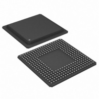
DS21FF42 Maxim Integrated Products, DS21FF42 Datasheet - Page 38

DS21FF42
Manufacturer Part Number
DS21FF42
Description
IC FRAMER T1 4X4 16CH 300-BGA
Manufacturer
Maxim Integrated Products
Datasheet
1.DS21FT42.pdf
(114 pages)
Specifications of DS21FF42
Controller Type
T1 Framer
Interface
Parallel/Serial
Voltage - Supply
2.97 V ~ 3.63 V
Current - Supply
300mA
Operating Temperature
0°C ~ 70°C
Mounting Type
Surface Mount
Package / Case
300-BGA
Lead Free Status / RoHS Status
Contains lead / RoHS non-compliant
Available stocks
Company
Part Number
Manufacturer
Quantity
Price
Company:
Part Number:
DS21FF42
Manufacturer:
LATTRON
Quantity:
9 020
PULSE DENSITY ENFORCER
The Framer always examines both the transmit and receive data streams for violations of the following
rules which are required by ANSI T1.403:
– No more than 15 consecutive zeros
– At least N ones in each and every time window of 8 x (N +1) bits where N = 1 through 23
Violations for the transmit and receive data streams are reported in the RIR2.0 and RIR2.1 bits
respectively. When the CCR3.3 is set to one, the DS21Q42 will force the transmitted stream to meet this
requirement no matter the content of the transmitted stream. When running B8ZS, the CCR3.3 bit should
be set to zero since B8ZS encoded data streams cannot violate the pulse density requirements.
CCR4: COMMON CONTROL REGISTER 4 (Address=11 Hex)
(MSB)
RSRE
SYMBOL
SYMBOL
TESMDM
RFSA1
RPCSI
RSRE
RFE
RPCSI
POSITION
POSITION
CCR3.0
CCR4.7
CCR4.6
CCR4.5
CCR4.4
RFSA1
NAME AND DESCRIPTION
NAME AND DESCRIPTION
Transmit Elastic Store Minimum Delay Mode. See
Section 17 for details.
0 = elastic stores operate at full two frame depth
1 = elastic stores operate at 32–bit depth
Receive Side Signaling Re–Insertion Enable. See Section
14 for details.
0 = do not re-insert signaling bits into the data stream
presented at the RSER pin
1 = reinsert the signaling bits into data stream presented at
the RSER pin
Receive Per–Channel Signaling Insert. See Section 14 for
more details.
0 = do not use RCHBLK to determine which channels should
have signaling re–inserted
1 = use RCHBLK to determine which channels should have
signaling re–inserted
Receive Force Signaling All Ones. See Section 14 for more
details.
0 = do not force extracted robbed–bit signaling bit positions
to a one
1 = force extracted robbed–bit signaling bit positions to a one
Receive Freeze Enable. See Section 14 for details.
0 = no freezing of receive signaling data will occur
1 = allow freezing of receive signaling data at RSIG (and
RSER if CCR4.7 = 1).
RFE
38 of 114
RFF
THSE
TPCSI
TIRFS
(LSB)


