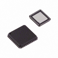
ADV7393BCPZ Analog Devices Inc, ADV7393BCPZ Datasheet - Page 60

ADV7393BCPZ
Manufacturer Part Number
ADV7393BCPZ
Description
IC DAC VIDEO HDTV 10BIT 40LFCSP
Manufacturer
Analog Devices Inc
Type
Video Encoderr
Datasheet
1.ADV7393BCPZ.pdf
(108 pages)
Specifications of ADV7393BCPZ
Design Resources
Reconstruction Video Filter Using ADA4430-1 Amplifier After ADV7393 Video Encoder (CN0101)
Applications
Set-Top Boxes, Video Players, Displays
Voltage - Supply, Analog
2.6 V ~ 3.46 V
Voltage - Supply, Digital
1.71 V ~ 1.89 V
Mounting Type
Surface Mount
Package / Case
40-LFCSP
Input Format
Digital
Output Format
Analog
Supply Voltage Range
1.71V To 1.89V
Operating Temperature Range
-40°C To +85°C
Tv / Video Case Style
LFCSP
No. Of Pins
40
Msl
MSL 1 - Unlimited
Lead Free Status / RoHS Status
Lead free / RoHS Compliant
For Use With
ADV7393-DBRDZ - BOARD EVAL FOR ADV7393EVAL-ADV7393EBZ - BOARD EVAL FOR ADV7393 ENCODER
Lead Free Status / RoHS Status
Lead free / RoHS Compliant, Lead free / RoHS Compliant
Available stocks
Company
Part Number
Manufacturer
Quantity
Price
Company:
Part Number:
ADV7393BCPZ
Manufacturer:
SIEMENS
Quantity:
101
Part Number:
ADV7393BCPZ
Manufacturer:
ADI/亚德诺
Quantity:
20 000
Company:
Part Number:
ADV7393BCPZ-3
Manufacturer:
ADI
Quantity:
302
Part Number:
ADV7393BCPZ-3
Manufacturer:
ADI/亚德诺
Quantity:
20 000
Company:
Part Number:
ADV7393BCPZ3
Manufacturer:
OSRAM
Quantity:
4 298
ADV7390/ADV7391/ADV7392/ADV7393
The gamma curves in Figure 74 and Figure 75 are examples only;
any user-defined curve in the range from 16 to 240 is acceptable.
ED/HD SHARPNESS FILTER AND ADAPTIVE FILTER
CONTROLS
Subaddress 0x40; Subaddress 0x58 to Subaddress 0x5D
There are three filter modes available on the ADV739x:
sharpness filter mode and two adaptive filter modes.
ED/HD Sharpness Filter Mode
To enhance or attenuate the Y signal in the frequency ranges
shown in Figure 76, the ED/HD sharpness filter must be
enabled (Subaddress 0x31, Bit 7 = 1) and the ED/HD adaptive
filter must be disabled (Subaddress 0x35, Bit 7 = 0).
Figure 74. Signal Input (Ramp) and Signal Output for Gamma 0.5
300
250
200
150
100
300
250
200
150
100
Figure 75. Signal Input (Ramp) and Selectable Output Curves
50
50
0
0
0
0
GAMMA CORRECTION BLOCK OUTPUT TO A RAMP INPUT
GAMMA CORRECTION BLOCK TO A RAMP INPUT FOR
50
50
SIGNAL INPUT
VARIOUS GAMMA VALUES
100
100
LOCATION
LOCATION
0.5
1.5
0.3
1.8
0.5
SIGNAL OUTPUT
150
150
200
200
250
250
Rev. B | Page 60 of 108
To select one of the 256 individual responses, the corresponding
gain values, ranging from −8 to +7 for each filter, must be
programmed into the ED/HD sharpness filter gain register at
Subaddress 0x40.
ED/HD Adaptive Filter Mode
In ED/HD adaptive filter mode, the following registers are used:
•
•
•
•
•
•
•
To activate the adaptive filter control, the ED/HD sharpness
filter and the ED/HD adaptive filter must be enabled
(Subaddress 0x31, Bit 7 = 1, and Subaddress 0x35, Bit 7 = 1,
respectively).
The derivative of the incoming signal is compared to the three
programmable threshold values: ED/HD adaptive filter
(Threshold A, Threshold B, and Threshold C ) registers
(Subaddress 0x5B, Subaddress 0x5C, and Subaddress 0x5D).
The recommended threshold range is 16 to 235, although any
value in the range of 0 to 255 can be used.
The edges can then be attenuated with the settings in the
ED/HD adaptive filter (Gain 1, Gain 2, and Gain 3) registers
(Subaddress 0x58, Subaddress 0x59 and Subaddress 0x5A), and
the ED/HD sharpness filter gain register (Subaddress 0x40).
There are two adaptive filter modes available. The mode is
selected using the ED/HD adaptive filter mode control
(Subaddress 0x35, Bit 6) as follows:
•
•
ED/HD Adaptive Filter Threshold A
ED/HD Adaptive Filter Threshold B
ED/HD Adaptive Filter Threshold C
ED/HD Adaptive Filter Gain 1
ED/HD Adaptive Filter Gain 2
ED/HD Adaptive Filter Gain 3
ED/HD sharpness filter gain
Mode A is used when the ED/HD adaptive filter mode
control is set to 0. In this case, Filter B (LPF) is used in the
adaptive filter block. In addition, only the programmed
values for Gain B in the ED/HD sharpness filter gain
register and ED/HD adaptive filter (Gain 1, Gain 2, and
Gain 3) registers are applied when needed. The Gain A
values are fixed and cannot be changed.
Mode B is used when ED/HD adaptive filter mode control is
set to 1. In this mode, a cascade of Filter A and Filter B is used.
Both settings for Gain A and Gain B in the ED/HD sharpness
filter gain register and ED/HD adaptive filter (Gain 1, Gain 2,
and Gain 3) registers become active when needed.


