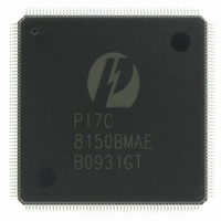
PI7C8150BMAE Pericom Semiconductor, PI7C8150BMAE Datasheet - Page 68

PI7C8150BMAE
Manufacturer Part Number
PI7C8150BMAE
Description
IC PCI-PCI BRIDGE ASYNC 208-FQFP
Manufacturer
Pericom Semiconductor
Datasheet
1.PI7C8150BNDE.pdf
(109 pages)
Specifications of PI7C8150BMAE
Applications
*
Interface
*
Voltage - Supply
*
Package / Case
208-FQFP
Mounting Type
Surface Mount
Maximum Operating Temperature
+ 85 C
Minimum Operating Temperature
0 C
Mounting Style
SMD/SMT
Operating Supply Voltage
3 V to 3.6 V
Supply Current (max)
510 mA
Lead Free Status / RoHS Status
Lead free / RoHS Compliant
Available stocks
Company
Part Number
Manufacturer
Quantity
Price
Part Number:
PI7C8150BMAE
Manufacturer:
PERICOM
Quantity:
20 000
10
10.1
To set asynchronous mode support, MS0 and MS1 must be configured accordingly:
When MS0 and MS1 are pulled to HIGH during the deassertion of P_RST, PI7C8150B
will go into asynchronous mode. The secondary clock outputs will then be derived from
ASYNC_CLKIN and not P_CLK. S_CLKOUT[9] is still connected to S_CLKIN to
provide the same timing as the bus clocks. CFG66/SCAN_EN_H becomes CLK_RATE in
asynchronous mode. Pulling CLK_RATE HIGH sets S_CLKOUT[9:0] equal to
ASYNC_CLKIN. Pulling CLK_RATE LOW sets S_CLKOUT[9:0] to half the frequency
of ASYNC_CLKIN. PI7C8150B will not be able to drive S_M66EN in asynchronous
mode.
GENERAL PURPOSE I/O INTERFACE
The PI7C8150B implements a 4-pin general purpose I/O interface. During normal
operation, device specific configuration registers control the GPIO interface. The GPIO
interface can be used for the following functions:
During normal operation, the following device specific configuration registers control the
GPIO interface:
These registers consist of five 8-bit fields:
GPIO CONTROL REGISTERS
During secondary interface reset, the GPIO interface can be used to shift in a 16-bit
serial stream that serves as a secondary bus clock disable mask.
Along with the GPIO[3] pin, a live insertion bit can be used to bring the PI7C8150B to
a halt through hardware, permitting live insertion of option cards behind the
PI7C8150B.
The GPIO output data register
The GPIO output enable control register
The GPIO input data register
Write-1-to-set output data field
Write-1-to-clear output data field
Write-1-to-set signal output enable control field
Write-1-to-clear signal output enable control field
MS0
0
0
1
1
Page 68 of 109
ASYNCHRONOUS 2-PORT PCI-TO-PCI BRIDGE
MS1
0
1
0
1
Reserved for future use
Reserved for future use
Synchronous Mode
Asynchronous Mode
ADVANCE INFORMATION
Description
April 2009 – Revision 1.08
PI7C8150B


