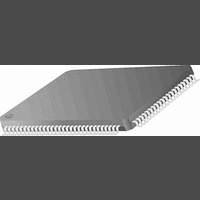
PC87393VJG National Semiconductor, PC87393VJG Datasheet - Page 5

PC87393VJG
Manufacturer Part Number
PC87393VJG
Description
IC, SUPER I/O DEVICE, TQFP-100
Manufacturer
National Semiconductor
Specifications of PC87393VJG
Data Rate
2Mbps
Supply Voltage Range
3V to 3.6V
Logic Case Style
TQFP
No. Of Pins
100
Operating Temperature Range
0°C to +70°C
Termination Type
SMD
Transceiver Type
Interface
Rohs Compliant
No
Available stocks
Company
Part Number
Manufacturer
Quantity
Price
Part Number:
PC87393VJG
Manufacturer:
NS/国半
Quantity:
20 000
Table of Contents
1.0
2.0
Signal/Pin Connection and Description
1.1
1.2
1.3
1.4
1.5
1.6
Device Architecture and Configuration
2.1
2.2
2.3
2.4
2.5
2.6
2.7
CONNECTION DIAGRAMS ...................................................................................................... 11
BUFFER TYPES AND SIGNAL/PIN DIRECTORY .................................................................... 15
PIN MULTIPLEXING ................................................................................................................. 15
PARALLEL PORT MULTIPLEXER (PPM) ................................................................................ 17
DETAILED SIGNAL/PIN DESCRIPTIONS ................................................................................ 18
1.5.1
1.5.2
1.5.3
1.5.4
1.5.5
1.5.6
1.5.7
1.5.8
1.5.9
1.5.10
1.5.11
1.5.12
1.5.13
1.5.14
INTERNAL PULL-UP AND PULL-DOWN RESISTORS ............................................................ 24
OVERVIEW ............................................................................................................................... 26
CONFIGURATION STRUCTURE AND ACCESS ..................................................................... 26
2.2.1
2.2.2
2.2.3
2.2.4
2.2.5
2.2.6
2.2.7
THE CLOCK MULTIPLIER ........................................................................................................ 33
2.3.1
2.3.2
2.3.3
2.3.4
INTERRUPT SERIALIZER ........................................................................................................ 34
WAKE-UP CONTROL ............................................................................................................... 34
THE PARALLEL PORT MULTIPLEXER (PPM) ........................................................................ 34
2.6.1
PROTECTION ........................................................................................................................... 36
2.7.1
Bus Interface ............................................................................................................... 18
Clock ............................................................................................................................ 18
Infrared (IR) ................................................................................................................ 18
Floppy Disk Controller (FDC) ..................................................................................... 19
Game Port (PC87393 and PC87393F) ....................................................................... 20
General-Purpose Input/Output (GPIO) Ports (PC87392, PC87393 and PC87393F)
Musical Instrument Digital Interface (MIDI) Port (PC87393 and PC87393F) ............ 20
Parallel Port ................................................................................................................ 21
Power and Ground ..................................................................................................... 21
Serial Port 1 and Serial Port 2 (SP1 and SP2) ............................................................ 22
Strap Configuration ...................................................................................................... 23
Wake-Up Control ......................................................................................................... 23
WATCHDOG Timer ..................................................................................................... 23
X-Bus Extension (PC87393 and PC87393F) ............................................................. 23
The Index-Data Register Pair ...................................................................................... 26
Banked Logical Device Registers Structure ................................................................ 28
Standard Logical Device Configuration Register Definitions ....................................... 29
Standard Configuration Registers ............................................................................... 31
Default Configuration Setup ........................................................................................ 32
Power States ............................................................................................................... 32
Address Decoding ....................................................................................................... 32
Functionality ................................................................................................................ 33
Chip Power-Up ............................................................................................................ 33
Disabling the Clock ...................................................................................................... 33
Specifications .............................................................................................................. 33
PPM Power Save Mode .............................................................................................. 35
Pin Configuration Lock ................................................................................................ 36
5
www.national.com
20


