MA240017 Microchip Technology, MA240017 Datasheet - Page 165
MA240017
Manufacturer Part Number
MA240017
Description
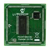
MODULE PLUG-IN PIC24F16KA102 PIM
Manufacturer
Microchip Technology
Series
PIC®r
Specifications of MA240017
Accessory Type
Plug-In Module (PIM) - PIC24F16KA102
Product
Microcontroller Modules
Data Bus Width
16 bit
Core Processor
PIC24F16KA102
Operating Supply Voltage
3 V to 3.6 V
Development Tools By Supplier
Integrated Development Environment, Assembler, ANSI C Compiler
Processor Series
PIC24F
Silicon Manufacturer
Microchip
Core Architecture
PIC
Core Sub-architecture
PIC24
Silicon Core Number
PIC24F
Silicon Family Name
PIC24FxxKAxx
Lead Free Status / RoHS Status
Lead free / RoHS Compliant
For Use With/related Products
Explorer 16 (DM240001 or DM240002)
For Use With
DM240001 - BOARD DEMO PIC24/DSPIC33/PIC32
Lead Free Status / Rohs Status
Lead free / RoHS Compliant
Available stocks
Company
Part Number
Manufacturer
Quantity
Price
Company:

Part Number:
MA240017
Manufacturer:
MICROCHIP
Quantity:
12 000


20.0
The programmable Cyclic Redundancy Check (CRC)
module in PIC24F devices is a software-configurable
CRC checksum generator. The CRC algorithm treats a
message as a binary bit stream and divides it by a fixed
binary number.
The remainder from this division is considered the
checksum. As in division, the CRC calculation is also
an iterative process. The only difference is that these
operations are done on modulo arithmetic based on
mod2. For example, division is replaced with the XOR
operation (i.e., subtraction without carry). The CRC
algorithm uses the term, polynomial, to perform all of
its calculations.
The divisor, dividend and remainder that are
represented by numbers are termed as polynomials
with binary coefficients.
FIGURE 20-1:
© 2009 Microchip Technology Inc.
Note:
D
PLEN<3:0>
OUT
XOR
PROGRAMMABLE CYCLIC
REDUNDANCY CHECK (CRC)
GENERATOR
This data sheet summarizes the features of
this group of PIC24F devices. It is not
intended to be a comprehensive reference
source. For more information on Program-
mable Cyclic Redundancy Check, refer to
the “PIC24F Family Reference Manual”,
Section
Redundancy Check (CRC)” (DS39714).
IN
clk
Hold
BIT 0
OUT
0
30.
CRC SHIFTER DETAILS
“Programmable
X1
0
1
IN
clk
Hold
BIT 1
OUT
1
Cyclic
CRC Shift Register
Preliminary
PIC24F16KA102 FAMILY
X2
0
1
CRC Write Bus
The programmable CRC generator offers the following
features:
• User-programmable polynomial CRC equation
• Interrupt output
• Data FIFO
The module implements a software-configurable CRC
generator. The terms of the polynomial and its length
can be programmed using the CRCXOR (X<15:1>) bits
and the CRCCON (PLEN<3:0>) bits, respectively.
Consider the CRC equation:
To program this polynomial into the CRC generator, the
CRC register bits should be set as provided in
Table 20-1.
TABLE 20-1:
The value of X<15:1>, the 12
to ‘1’, as required by the equation. The 0 bit required by
the equation is always XORed. For a 16-bit polynomial,
the 16
therefore, the X<15:1> bits do not have the 0 bit or the
16
The topology of a standard CRC generator is displayed
in Figure 20-2.
PLEN<3:0>
X<15:1>
IN
clk
Hold
BIT 2
th
OUT
Bit Name
bit.
th
2
bit is also always assumed to be XORed;
CRC Read Bus
EXAMPLE CRC SETUP
X3
x
0
1
16
+ x
X15
12
000100000010000
0
1
+ x
th
bit and the 5
5
Bit Value
+ 1
IN
BIT 15
clk
1111
Hold
OUT
DS39927B-page 163
15
th
bit are set
Related parts for MA240017
Image
Part Number
Description
Manufacturer
Datasheet
Request
R

Part Number:
Description:
Manufacturer:
Microchip Technology Inc.
Datasheet:
Part Number:
Description:
Manufacturer:
Microchip Technology Inc.
Datasheet:
Part Number:
Description:
Manufacturer:
Microchip Technology Inc.
Datasheet:
Part Number:
Description:
Manufacturer:
Microchip Technology Inc.
Datasheet:
Part Number:
Description:
Manufacturer:
Microchip Technology Inc.
Datasheet:
Part Number:
Description:
Manufacturer:
Microchip Technology Inc.
Datasheet:
Part Number:
Description:
Manufacturer:
Microchip Technology Inc.
Datasheet:
Part Number:
Description:
Manufacturer:
Microchip Technology Inc.
Datasheet: