MA240017 Microchip Technology, MA240017 Datasheet - Page 94
MA240017
Manufacturer Part Number
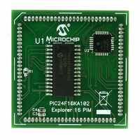
MA240017
Description
MODULE PLUG-IN PIC24F16KA102 PIM
Manufacturer
Microchip Technology
Series
PIC®r
Specifications of MA240017
Accessory Type
Plug-In Module (PIM) - PIC24F16KA102
Product
Microcontroller Modules
Data Bus Width
16 bit
Core Processor
PIC24F16KA102
Operating Supply Voltage
3 V to 3.6 V
Development Tools By Supplier
Integrated Development Environment, Assembler, ANSI C Compiler
Processor Series
PIC24F
Silicon Manufacturer
Microchip
Core Architecture
PIC
Core Sub-architecture
PIC24
Silicon Core Number
PIC24F
Silicon Family Name
PIC24FxxKAxx
Lead Free Status / RoHS Status
Lead free / RoHS Compliant
For Use With/related Products
Explorer 16 (DM240001 or DM240002)
For Use With
DM240001 - BOARD DEMO PIC24/DSPIC33/PIC32
Lead Free Status / Rohs Status
Lead free / RoHS Compliant
Available stocks
Company
Part Number
Manufacturer
Quantity
Price
Company:

Part Number:
MA240017
Manufacturer:
MICROCHIP
Quantity:
12 000


PIC24F16KA102 FAMILY
9.1
The system clock source can be provided by one of
four sources:
• Primary Oscillator (POSC) on the OSCI and OSCO
• Secondary Oscillator (SOSC) on the SOSCI and
• Fast Internal RC (FRC) Oscillator
• Low-Power Internal RC (LPRC) Oscillator
The primary oscillator and 8 MHz FRC sources have
the option of using the internal 4x PLL. The frequency
of the FRC clock source can optionally be reduced by
the programmable clock divider. The selected clock
source generates the processor and peripheral clock
sources.
The processor clock source is divided by two to produce
the internal instruction cycle clock, F
ment, the instruction cycle clock is also denoted by
F
be provided on the OSCO I/O pin for some operating
modes of the primary oscillator.
TABLE 9-1:
DS39927B-page 92
8 MHz FRC Oscillator with Postscaler
(FRCDIV)
500 MHz FRC Oscillator with Postscaler
(LPFRCDIV)
Low-Power RC Oscillator (LPRC)
Secondary (Timer1) Oscillator (SOSC)
Primary Oscillator (HS) with PLL Module
(HSPLL)
Primary Oscillator (EC) with PLL Module
(ECPLL)
Primary Oscillator (HS)
Primary Oscillator (XT)
Primary Oscillator (EC)
8 MHz FRC Oscillator with PLL Module
(FRCPLL)
8 MHz FRC Oscillator (FRC)
Note 1:
OSC
pins
SOSCO pins
The PIC24F16KA102 family devices consist of two
types of secondary oscillator:
- High-Power Secondary Oscillator
- Low-Power Secondary Oscillator
These can be selected by using the SOSCSEL
(FOSC<5>) bit.
- 8 MHz FRC Oscillator
- 500 kHz Lower Power FRC Oscillator
/2. The internal instruction cycle clock, F
2:
CPU Clocking Scheme
OSCO pin function is determined by the OSCIOFNC Configuration bit.
This is the default oscillator mode for an unprogrammed (erased) device.
Oscillator Mode
CONFIGURATION BIT VALUES FOR CLOCK SELECTION
CY
. In this docu-
OSC
Oscillator Source
/2, can
Secondary
Preliminary
Primary
Primary
Primary
Primary
Primary
Internal
Internal
Internal
Internal
Internal
Configuration bit settings are located in the Configuration
9.2
The oscillator source (and operating mode) that is used
at a device Power-on Reset (POR) event is selected
using
registers in the program memory (refer to Section 26.1
“Configuration Bits” for further details). The Primary
Oscillator
(FOSC<1:0>), and the Initial Oscillator Select Configura-
tion bits, FNOSC<2:0> (FOSCSEL<2:0>), select the
oscillator source that is used at a POR. The FRC primary
oscillator with postscaler (FRCDIV) is the default (unpro-
grammed) selection. The secondary oscillator, or one of
the internal oscillators, may be chosen by programming
these bit locations. The EC mode frequency range
Configuration bits, POSCFREQ<1:0> (FOSC<4:3>),
optimize power consumption when running in EC
mode. The default configuration is “frequency range is
greater than 8 MHz”.
The Configuration bits allow users to choose between
the various clock modes, shown in Table 9-1.
9.2.1
The FCKSM Configuration bits (FOSC<7:6>) are used
jointly to configure device clock switching and the
FSCM. Clock switching is enabled only when FCKSM1
is programmed (‘0’). The FSCM is enabled only when
FCKSM<1:0> are both programmed (‘00’).
POSCMD<1:0>
Configuration
Initial Configuration on POR
11
11
11
00
10
00
10
01
00
11
11
CLOCK SWITCHING MODE
CONFIGURATION BITS
Configuration
bit
© 2009 Microchip Technology Inc.
FNOSC<2:0>
settings.
111
110
101
100
011
011
010
010
010
001
000
bits,
POSCMD<1:0>
The
Note
oscillator
1, 2
1
1
1
1
1
Related parts for MA240017
Image
Part Number
Description
Manufacturer
Datasheet
Request
R

Part Number:
Description:
Manufacturer:
Microchip Technology Inc.
Datasheet:
Part Number:
Description:
Manufacturer:
Microchip Technology Inc.
Datasheet:
Part Number:
Description:
Manufacturer:
Microchip Technology Inc.
Datasheet:
Part Number:
Description:
Manufacturer:
Microchip Technology Inc.
Datasheet:
Part Number:
Description:
Manufacturer:
Microchip Technology Inc.
Datasheet:
Part Number:
Description:
Manufacturer:
Microchip Technology Inc.
Datasheet:
Part Number:
Description:
Manufacturer:
Microchip Technology Inc.
Datasheet:
Part Number:
Description:
Manufacturer:
Microchip Technology Inc.
Datasheet: