MA240017 Microchip Technology, MA240017 Datasheet - Page 68
MA240017
Manufacturer Part Number
MA240017
Description
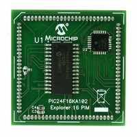
MODULE PLUG-IN PIC24F16KA102 PIM
Manufacturer
Microchip Technology
Series
PIC®r
Specifications of MA240017
Accessory Type
Plug-In Module (PIM) - PIC24F16KA102
Product
Microcontroller Modules
Data Bus Width
16 bit
Core Processor
PIC24F16KA102
Operating Supply Voltage
3 V to 3.6 V
Development Tools By Supplier
Integrated Development Environment, Assembler, ANSI C Compiler
Processor Series
PIC24F
Silicon Manufacturer
Microchip
Core Architecture
PIC
Core Sub-architecture
PIC24
Silicon Core Number
PIC24F
Silicon Family Name
PIC24FxxKAxx
Lead Free Status / RoHS Status
Lead free / RoHS Compliant
For Use With/related Products
Explorer 16 (DM240001 or DM240002)
For Use With
DM240001 - BOARD DEMO PIC24/DSPIC33/PIC32
Lead Free Status / Rohs Status
Lead free / RoHS Compliant
Available stocks
Company
Part Number
Manufacturer
Quantity
Price
Company:

Part Number:
MA240017
Manufacturer:
MICROCHIP
Quantity:
12 000


PIC24F16KA102 FAMILY
8.3
The PIC24F16KA102 family of devices implements a
total of 22 registers for the interrupt controller:
• INTCON1
• INTCON2
• IFS0, IFS1, IFS3 and IFS4
• IEC0, IEC1, IEC3 and IEC4
• IPC0 through IPC5, IPC7 and IPC15 through
• INTTREG
Global interrupt control functions are controlled from
INTCON1 and INTCON2. INTCON1 contains the
Interrupt Nesting Disable (NSTDIS) bit, as well as the
control and status flags for the processor trap sources.
The INTCON2 register controls the external interrupt
request signal behavior and the use of the AIV table.
The IFSx registers maintain all of the interrupt request
flags. Each source of interrupt has a status bit, which is
set by the respective peripherals, or external signal,
and is cleared via software.
The IECx registers maintain all of the interrupt enable
bits. These control bits are used to individually enable
interrupts from the peripherals or external signals.
The IPCx registers are used to set the interrupt priority
level for each source of interrupt. Each user interrupt
source can be assigned to one of eight priority levels.
DS39927B-page 66
IPC19
Interrupt Control and Status
Registers
Preliminary
The INTTREG register contains the associated inter-
rupt vector number and the new CPU interrupt priority
level, which are latched into the Vector Number
(VECNUM<6:0>) and the Interrupt Level (ILR<3:0>) bit
fields in the INTTREG register. The new interrupt
priority level is the priority of the pending interrupt.
The interrupt sources are assigned to the IFSx, IECx
and IPCx registers in the same sequence listed in
Table 8-2. For example, the INT0 (External Interrupt 0)
is depicted as having a vector number and a natural
order priority of 0. Thus, the INT0IF status bit is found
in IFS0<0>, the INT0IE enable bit in IEC0<0> and the
INT0IP<2:0> priority bits in the first position of IPC0
(IPC0<2:0>).
Although they are not specifically part of the interrupt
control hardware, two of the CPU control registers
contain bits that control interrupt functionality. The ALU
STATUS register (SR) contains the IPL<2:0> bits
(SR<7:5>). These indicate the current CPU interrupt
priority level. The user may change the current CPU
priority level by writing to the IPL bits.
The CORCON register contains the IPL3 bit, which
together with IPL<2:0>, also indicates the current CPU
priority level. IPL3 is a read-only bit so that the trap
events cannot be masked by the user’s software.
All interrupt registers are described in Register 8-1
through Register 8-21, in the following sections.
© 2009 Microchip Technology Inc.
Related parts for MA240017
Image
Part Number
Description
Manufacturer
Datasheet
Request
R

Part Number:
Description:
Manufacturer:
Microchip Technology Inc.
Datasheet:
Part Number:
Description:
Manufacturer:
Microchip Technology Inc.
Datasheet:
Part Number:
Description:
Manufacturer:
Microchip Technology Inc.
Datasheet:
Part Number:
Description:
Manufacturer:
Microchip Technology Inc.
Datasheet:
Part Number:
Description:
Manufacturer:
Microchip Technology Inc.
Datasheet:
Part Number:
Description:
Manufacturer:
Microchip Technology Inc.
Datasheet:
Part Number:
Description:
Manufacturer:
Microchip Technology Inc.
Datasheet:
Part Number:
Description:
Manufacturer:
Microchip Technology Inc.
Datasheet: