MA240017 Microchip Technology, MA240017 Datasheet - Page 25
MA240017
Manufacturer Part Number
MA240017
Description
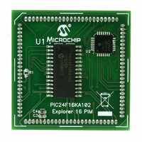
MODULE PLUG-IN PIC24F16KA102 PIM
Manufacturer
Microchip Technology
Series
PIC®r
Specifications of MA240017
Accessory Type
Plug-In Module (PIM) - PIC24F16KA102
Product
Microcontroller Modules
Data Bus Width
16 bit
Core Processor
PIC24F16KA102
Operating Supply Voltage
3 V to 3.6 V
Development Tools By Supplier
Integrated Development Environment, Assembler, ANSI C Compiler
Processor Series
PIC24F
Silicon Manufacturer
Microchip
Core Architecture
PIC
Core Sub-architecture
PIC24
Silicon Core Number
PIC24F
Silicon Family Name
PIC24FxxKAxx
Lead Free Status / RoHS Status
Lead free / RoHS Compliant
For Use With/related Products
Explorer 16 (DM240001 or DM240002)
For Use With
DM240001 - BOARD DEMO PIC24/DSPIC33/PIC32
Lead Free Status / Rohs Status
Lead free / RoHS Compliant
Available stocks
Company
Part Number
Manufacturer
Quantity
Price
Company:

Part Number:
MA240017
Manufacturer:
MICROCHIP
Quantity:
12 000


REGISTER 3-2:
3.3
The PIC24F ALU is 16 bits wide and is capable of
addition, subtraction, bit shifts and logic operations.
Unless otherwise mentioned, arithmetic operations are
2’s complement in nature. Depending on the operation,
the ALU may affect the values of the Carry (C), Zero
(Z), Negative (N), Overflow (OV) and Digit Carry (DC)
Status bits in the SR register. The C and DC Status bits
operate as Borrow and Digit Borrow bits, respectively,
for subtraction operations.
The ALU can perform 8-bit or 16-bit operations,
depending on the mode of the instruction that is used.
Data for the ALU operation can come from the W
register array, or data memory, depending on the
addressing mode of the instruction. Likewise, output
data from the ALU can be written to the W register array
or a data memory location.
© 2009 Microchip Technology Inc.
bit 15
bit 7
Legend:
R = Readable bit
-n = Value at POR
bit 15-4
bit 3
bit 2
bit 1-0
Note 1:
U-0
U-0
—
—
Arithmetic Logic Unit (ALU)
User interrupts are disabled when IPL3 = 1.
Unimplemented: Read as ‘0’
IPL3: CPU Interrupt Priority Level Status bit
1 = CPU interrupt priority level is greater than 7
0 = CPU interrupt priority level is 7 or less
PSV: Program Space Visibility in Data Space Enable bit
1 = Program space visible in data space
0 = Program space not visible in data space
Unimplemented: Read as ‘0’
U-0
U-0
—
—
CORCON: CPU CONTROL REGISTER
HSC = Hardware Settable/Clearable bit
W = Writable bit
‘1’ = Bit is set
U-0
U-0
—
—
U-0
U-0
—
—
Preliminary
PIC24F16KA102 FAMILY
(1)
U = Unimplemented bit, read as ‘0’
‘0’ = Bit is cleared
R/C-0, HSC
IPL3
The PIC24F CPU incorporates hardware support for
both multiplication and division. This includes a
dedicated hardware multiplier and support hardware
division for 16-bit divisor.
3.3.1
The ALU contains a high-speed, 17-bit x 17-bit
multiplier. It supports unsigned, signed or mixed sign
operation in several multiplication modes:
• 16-bit x 16-bit signed
• 16-bit x 16-bit unsigned
• 16-bit signed x 5-bit (literal) unsigned
• 16-bit unsigned x 16-bit unsigned
• 16-bit unsigned x 5-bit (literal) unsigned
• 16-bit unsigned x 16-bit signed
• 8-bit unsigned x 8-bit unsigned
U-0
—
(1)
MULTIPLIER
R/W-0
PSV
U-0
—
x = Bit is unknown
U-0
U-0
—
—
DS39927B-page 23
U-0
U-0
—
—
bit 8
bit 0
Related parts for MA240017
Image
Part Number
Description
Manufacturer
Datasheet
Request
R

Part Number:
Description:
Manufacturer:
Microchip Technology Inc.
Datasheet:
Part Number:
Description:
Manufacturer:
Microchip Technology Inc.
Datasheet:
Part Number:
Description:
Manufacturer:
Microchip Technology Inc.
Datasheet:
Part Number:
Description:
Manufacturer:
Microchip Technology Inc.
Datasheet:
Part Number:
Description:
Manufacturer:
Microchip Technology Inc.
Datasheet:
Part Number:
Description:
Manufacturer:
Microchip Technology Inc.
Datasheet:
Part Number:
Description:
Manufacturer:
Microchip Technology Inc.
Datasheet:
Part Number:
Description:
Manufacturer:
Microchip Technology Inc.
Datasheet: