MA240017 Microchip Technology, MA240017 Datasheet - Page 171
MA240017
Manufacturer Part Number
MA240017
Description
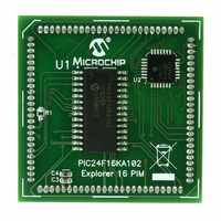
MODULE PLUG-IN PIC24F16KA102 PIM
Manufacturer
Microchip Technology
Series
PIC®r
Specifications of MA240017
Accessory Type
Plug-In Module (PIM) - PIC24F16KA102
Product
Microcontroller Modules
Data Bus Width
16 bit
Core Processor
PIC24F16KA102
Operating Supply Voltage
3 V to 3.6 V
Development Tools By Supplier
Integrated Development Environment, Assembler, ANSI C Compiler
Processor Series
PIC24F
Silicon Manufacturer
Microchip
Core Architecture
PIC
Core Sub-architecture
PIC24
Silicon Core Number
PIC24F
Silicon Family Name
PIC24FxxKAxx
Lead Free Status / RoHS Status
Lead free / RoHS Compliant
For Use With/related Products
Explorer 16 (DM240001 or DM240002)
For Use With
DM240001 - BOARD DEMO PIC24/DSPIC33/PIC32
Lead Free Status / Rohs Status
Lead free / RoHS Compliant
Available stocks
Company
Part Number
Manufacturer
Quantity
Price
Company:

Part Number:
MA240017
Manufacturer:
MICROCHIP
Quantity:
12 000


22.0
The 10-bit A/D Converter has the following key
features:
• Successive Approximation (SAR) conversion
• Conversion speeds of up to 500 ksps
• 9 analog input pins
• External voltage reference input pins
• Internal band gap reference inputs
• Automatic Channel Scan mode
• Selectable conversion trigger source
• 16-word conversion result buffer
• Selectable Buffer Fill modes
• Four result alignment options
• Operation during CPU Sleep and Idle modes
On all PIC24F16KA102 family devices, the 10-bit A/D
Converter has nine analog input pins, designated AN0
through AN5 and AN10 through AN12. In addition,
there are two analog input pins for external voltage
reference connections (V
voltage reference inputs may be shared with other
analog input pins.
© 2009 Microchip Technology Inc.
Note:
10-BIT HIGH-SPEED A/D
CONVERTER
This data sheet summarizes the features
of this group of PIC24F devices. It is not
intended to be a comprehensive reference
source. For more information on the 10-Bit
High-Speed A/D Converter, refer to the
“PIC24F
Section 17. “10-Bit A/D Converter”
(DS39705).
Family
REF
+ and V
Reference
REF
-). These
Manual”,
Preliminary
PIC24F16KA102 FAMILY
A block diagram of the A/D Converter is displayed in
Figure 22-1.
To perform an A/D conversion:
1.
2.
Configure the A/D module:
a)
b)
c)
d)
e)
f)
g)
Configure A/D interrupt (if required):
a)
b)
Configure port pins as analog inputs and/or
select
(AD1PCFG<15:13>, AD1PCFG<9:6>).
Select voltage reference source to match
expected
(AD1CON2<15:13>).
Select the analog conversion clock to match
the desired data rate with the processor
clock (AD1CON3<7:0>).
Select the appropriate sample/conversion
sequence
AD1CON3<12:8>).
Select
presented in the buffer (AD1CON1<9:8>).
Select interrupt rate (AD1CON2<5:2>).
Turn on A/D module (AD1CON1<15>).
Clear the AD1IF bit.
Select A/D interrupt priority.
band
how
range
(AD1CON1<7:5>
conversion
gap
on
reference
DS39927B-page 169
analog
results
inputs
inputs
and
are
Related parts for MA240017
Image
Part Number
Description
Manufacturer
Datasheet
Request
R

Part Number:
Description:
Manufacturer:
Microchip Technology Inc.
Datasheet:
Part Number:
Description:
Manufacturer:
Microchip Technology Inc.
Datasheet:
Part Number:
Description:
Manufacturer:
Microchip Technology Inc.
Datasheet:
Part Number:
Description:
Manufacturer:
Microchip Technology Inc.
Datasheet:
Part Number:
Description:
Manufacturer:
Microchip Technology Inc.
Datasheet:
Part Number:
Description:
Manufacturer:
Microchip Technology Inc.
Datasheet:
Part Number:
Description:
Manufacturer:
Microchip Technology Inc.
Datasheet:
Part Number:
Description:
Manufacturer:
Microchip Technology Inc.
Datasheet: