MA240017 Microchip Technology, MA240017 Datasheet - Page 28
MA240017
Manufacturer Part Number
MA240017
Description
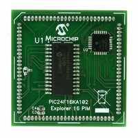
MODULE PLUG-IN PIC24F16KA102 PIM
Manufacturer
Microchip Technology
Series
PIC®r
Specifications of MA240017
Accessory Type
Plug-In Module (PIM) - PIC24F16KA102
Product
Microcontroller Modules
Data Bus Width
16 bit
Core Processor
PIC24F16KA102
Operating Supply Voltage
3 V to 3.6 V
Development Tools By Supplier
Integrated Development Environment, Assembler, ANSI C Compiler
Processor Series
PIC24F
Silicon Manufacturer
Microchip
Core Architecture
PIC
Core Sub-architecture
PIC24
Silicon Core Number
PIC24F
Silicon Family Name
PIC24FxxKAxx
Lead Free Status / RoHS Status
Lead free / RoHS Compliant
For Use With/related Products
Explorer 16 (DM240001 or DM240002)
For Use With
DM240001 - BOARD DEMO PIC24/DSPIC33/PIC32
Lead Free Status / Rohs Status
Lead free / RoHS Compliant
Available stocks
Company
Part Number
Manufacturer
Quantity
Price
Company:

Part Number:
MA240017
Manufacturer:
MICROCHIP
Quantity:
12 000


PIC24F16KA102 FAMILY
4.1.1
The
word-addressable blocks. Although it is treated as
24 bits wide, it is more appropriate to think of each
address of the program memory as a lower and upper
word, with the upper byte of the upper word being
unimplemented. The lower word always has an even
address, while the upper word has an odd address
(Figure 4-2).
Program memory addresses are always word-aligned
on the lower word, and addresses are incremented or
decremented by two during code execution. This
arrangement also provides compatibility with data
memory space addressing and makes it possible to
access data in the program memory space.
4.1.2
All PIC24F devices reserve the addresses between
00000h and 000200h for hard coded program
execution vectors. A hardware Reset vector is provided
to redirect code execution from the default value of the
PC on device Reset to the actual start of code. A GOTO
instruction is programmed by the user at 000000h with
the actual address for the start of code at 000002h.
PIC24F devices also have two interrupt vector
tables, located from 000004h to 0000FFh and
000104h to 0001FFh. These vector tables allow each
of the many device interrupt sources to be handled
by separate ISRs. Section 8.1 “Interrupt Vector
(IVT) Table” discusses the interrupt vector tables
more in detail.
FIGURE 4-2:
DS39927B-page 26
program
PROGRAM MEMORY
ORGANIZATION
HARD MEMORY VECTORS
Address
000001h
000003h
000005h
000007h
memory
msw
PROGRAM MEMORY ORGANIZATION
space
Program Memory
‘Phantom’ Byte
(read as ‘0’)
00000000
00000000
00000000
00000000
most significant word
is
organized
23
Preliminary
in
16
Instruction Width
4.1.3
In the PIC24F16KA102 family, the data EEPROM is
mapped to the top of the user program memory space,
starting at address 7FFE00 and expanding up to
address 7FFFFF.
The data EEPROM is organized as 16-bit wide memory
and 256 words deep. This memory is accessed using
table read and write operations similar to the user code
memory.
4.1.4
Table 4-1 provides the addresses of the device Config-
uration Words for the PIC24F16KA102 family. Their
location in the memory map is displayed in Figure 4-1.
Refer to Section 26.1 “Configuration Bits” for more
information on device Configuration Words.
TABLE 4-1:
least significant word
FBS
FGS
FOSCSEL
FOSC
FWDT
FPOR
FICD
FDS
Configuration Word
8
DATA EEPROM
DEVICE CONFIGURATION WORDS
DEVICE CONFIGURATION
WORDS FOR PIC24F16KA102
FAMILY DEVICES
0
© 2009 Microchip Technology Inc.
(lsw Address)
PC Address
000000h
000002h
000004h
000006h
Configuration Word
Addresses
F8000C
F80000
F80004
F80008
F8000A
F8000E
F80010
F80006
Related parts for MA240017
Image
Part Number
Description
Manufacturer
Datasheet
Request
R

Part Number:
Description:
Manufacturer:
Microchip Technology Inc.
Datasheet:
Part Number:
Description:
Manufacturer:
Microchip Technology Inc.
Datasheet:
Part Number:
Description:
Manufacturer:
Microchip Technology Inc.
Datasheet:
Part Number:
Description:
Manufacturer:
Microchip Technology Inc.
Datasheet:
Part Number:
Description:
Manufacturer:
Microchip Technology Inc.
Datasheet:
Part Number:
Description:
Manufacturer:
Microchip Technology Inc.
Datasheet:
Part Number:
Description:
Manufacturer:
Microchip Technology Inc.
Datasheet:
Part Number:
Description:
Manufacturer:
Microchip Technology Inc.
Datasheet: