AT91SAM7S32B-MU Atmel, AT91SAM7S32B-MU Datasheet - Page 561
AT91SAM7S32B-MU
Manufacturer Part Number
AT91SAM7S32B-MU
Description
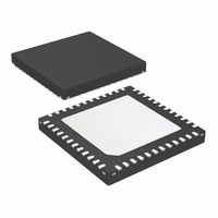
IC MCU ARM7 32KB FLASH 48-VQFN
Manufacturer
Atmel
Series
AT91SAMr
Datasheet
1.AT91SAM7S16-MU.pdf
(779 pages)
Specifications of AT91SAM7S32B-MU
Core Processor
ARM7
Core Size
16/32-Bit
Speed
55MHz
Connectivity
I²C, SPI, SSC, UART/USART
Peripherals
Brown-out Detect/Reset, DMA, POR, PWM, WDT
Number Of I /o
21
Program Memory Size
32KB (32K x 8)
Program Memory Type
FLASH
Ram Size
8K x 8
Voltage - Supply (vcc/vdd)
1.65 V ~ 1.95 V
Data Converters
A/D 8x10b
Oscillator Type
Internal
Operating Temperature
-40°C ~ 85°C
Package / Case
48-VQFN Exposed Pad, 48-HVQFN, 48-SQFN, 48-DHVQFN
For Use With
AT91SAM-ICE - EMULATOR FOR AT91 ARM7/ARM9AT91SAM7S-EK - KIT EVAL FOR ARM AT91SAM7S
Lead Free Status / RoHS Status
Lead free / RoHS Compliant
Eeprom Size
-
Available stocks
Company
Part Number
Manufacturer
Quantity
Price


6175K–ATARM–30-Aug-10
Table 37-7.
Note:
Mode
Active, Running out of SRAM, 1.1MHz
(AT91SAM7S64/321/32/161/16)
Active, Running out of SRAM, 1MHz
(AT91SAM7S512/256/128)
Ultra low power
1. “Flash is in standby mode” means the Flash is not accessed at all.
Low power consumption figures found in the above table cannot be guaranteed when access-
ing the Flash in Ultra Low Power Mode. In order to meet given low power consumption figures,
it is recommended to either stop the processor or jump to SRAM.
Power Consumption for Different Modes
AT91SAM7S Series Preliminary
Conditions
Voltage regulator is on.
Brown Out Detector is activated.
Flash is in standby mode.
PLL is de-activated.
Main oscillator is activated.
ARM Core clock is 1.1 MHz.
Running out of SRAM
Analog-to-Digital Converter activated.
All peripheral clocks activated.
USB transceiver enabled.
onto AMP1
onto AMP2
Voltage regulator is on.
Brown Out Detector is activated.
Flash is in standby mode.
PLL is de-activated.
Main oscillator is activated.
ARM Core clock is 1 MHz.
Running out of SRAM
Analog-to-Digital Converter activated.
All peripheral clocks activated.
USB transceiver enabled.
onto AMP1
onto AMP2
Voltage regulator is in Low-power
mode.
Brown Out Detector is de-activated.
Flash is in standby mode.
PLL is de-activated.
Main oscillator is activated.
ARM Core in idle mode.
MCK @ 500Hz.
Analog-to-Digital Converter de-
activated.
All peripheral clocks de-activated.
USB transceiver disabled.
DDM and DDP pins connected to
ground.
onto AMP1
onto AMP2
(1)
Consumption
1.12
1.06
1.06
0.99
34.3
4.0
Unit
mA
mA
µA
561
Related parts for AT91SAM7S32B-MU
Image
Part Number
Description
Manufacturer
Datasheet
Request
R

Part Number:
Description:
KIT EVAL FOR ARM AT91SAM7S
Manufacturer:
Atmel
Datasheet:

Part Number:
Description:
MCU, MPU & DSP Development Tools KICKSTART KIT ATMEL AT91SAM7S
Manufacturer:
IAR Systems

Part Number:
Description:
DEV KIT FOR AVR/AVR32
Manufacturer:
Atmel
Datasheet:

Part Number:
Description:
INTERVAL AND WIPE/WASH WIPER CONTROL IC WITH DELAY
Manufacturer:
ATMEL Corporation
Datasheet:
Part Number:
Description:
Low-Voltage Voice-Switched IC for Hands-Free Operation
Manufacturer:
ATMEL Corporation
Datasheet:
Part Number:
Description:
MONOLITHIC INTEGRATED FEATUREPHONE CIRCUIT
Manufacturer:
ATMEL Corporation
Datasheet:
Part Number:
Description:
AM-FM Receiver IC U4255BM-M
Manufacturer:
ATMEL Corporation
Datasheet:
Part Number:
Description:
Monolithic Integrated Feature Phone Circuit
Manufacturer:
ATMEL Corporation
Datasheet:
Part Number:
Description:
Multistandard Video-IF and Quasi Parallel Sound Processing
Manufacturer:
ATMEL Corporation
Datasheet:
Part Number:
Description:
High-performance EE PLD
Manufacturer:
ATMEL Corporation
Datasheet:
Part Number:
Description:
8-bit Flash Microcontroller
Manufacturer:
ATMEL Corporation
Datasheet:
Part Number:
Description:
2-Wire Serial EEPROM
Manufacturer:
ATMEL Corporation
Datasheet: