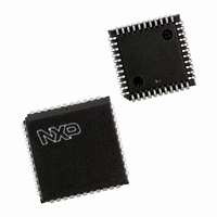
P87C591VFA/00,512 NXP Semiconductors, P87C591VFA/00,512 Datasheet - Page 140

P87C591VFA/00,512
Manufacturer Part Number
P87C591VFA/00,512
Description
IC 80C51 MCU 16K OTP 44-PLCC
Manufacturer
NXP Semiconductors
Series
87Cr
Datasheet
1.P87C591VFA00512.pdf
(160 pages)
Specifications of P87C591VFA/00,512
Core Processor
8051
Core Size
8-Bit
Speed
12MHz
Connectivity
CAN, EBI/EMI, I²C, UART/USART
Peripherals
POR, PWM, WDT
Number Of I /o
32
Program Memory Size
16KB (16K x 8)
Program Memory Type
OTP
Ram Size
512 x 8
Voltage - Supply (vcc/vdd)
4.75 V ~ 5.25 V
Data Converters
A/D 6x10b
Oscillator Type
Internal
Operating Temperature
-40°C ~ 85°C
Package / Case
44-PLCC
Processor Series
P87C5x
Core
80C51
Data Bus Width
8 bit
Data Ram Size
512 B
Interface Type
CAN, I2C, UART
Maximum Clock Frequency
12 MHz
Number Of Programmable I/os
32
Number Of Timers
3
Maximum Operating Temperature
+ 85 C
Mounting Style
SMD/SMT
3rd Party Development Tools
PK51, CA51, A51, ULINK2
Minimum Operating Temperature
- 40 C
On-chip Adc
10 bit, 6 Channel
Lead Free Status / RoHS Status
Lead free / RoHS Compliant
Eeprom Size
-
Lead Free Status / Rohs Status
Details
Other names
568-1256-5
935268182512
P87C591VFAA
935268182512
P87C591VFAA
Available stocks
Company
Part Number
Manufacturer
Quantity
Price
Company:
Part Number:
P87C591VFA/00,512
Manufacturer:
TI
Quantity:
8
Company:
Part Number:
P87C591VFA/00,512
Manufacturer:
NXP Semiconductors
Quantity:
10 000
Philips Semiconductors
Table 111 Description of the mnemonics in the Instruction set
22.1
Most instructions have a ‘destination, source’ field that
specifies the data type, addressing modes and operands
involved. For all these instructions, except for MOVs, the
destination operand is also the source operand
(e.g. ADD A,R7).
There are five kinds of addressing modes:
2000 Jul 26
MNEMONIC
Data addressing modes
Rr
direct
@Ri
#data
#data 16
bit
addr16
addr11
rel
Hexadecimal opcode cross-reference
*
Register Addressing
– R0 - R7 (4 banks)
– A,B,C (bit), AB (2 bytes), DPTR (double byte)
Direct Addressing
– lower 128 bytes of internal Main RAM (including the
– Special Function Registers
– 128 bits in a subset of the internal Main RAM
– 128 bits in a subset of the Special Function Registers
Register-Indirect Addressing
– internal Main RAM (@R0, @R1, @SP [PUSH/POP])
– internal Auxiliary RAM (@R0, @R1, @DPTR)
– external Data Memory (@R0, @R1, @DPTR)
Single-chip 8-bit microcontroller with CAN controller
4 R0-R7 register banks)
Addressing Modes
Working register R0-R7.
128 internal RAM locations and any special function register (SFR).
Indirect internal RAM location addressed by register R0 or R1 of the actual register bank.
8-bit constant included in instruction.
16-bit constant included as bytes 2 and 3 of instruction.
Direct addressed bit in internal RAM or SFR.
16-bit destination address. Used by LCALL and LJMP.
The branch will be anywhere within the 64 Kbytes Program Memory address space.
11-bit destination address. Used by ACALL and AJMP. The branch will be within the same 2 Kbytes
page of Program Memory as the first byte of the following instruction.
Signed (two's complement) 8-bit offset byte. Used by SJMP and all conditional jumps.
Range is 128 to +127 bytes relative to first byte of the following instruction.
8, 9, A, B, C, D, E, F.
1, 3, 5, 7, 9, B, D, F.
0, 2, 4, 6, 8, A, C, E.
140
DESCRIPTION
The first three addressing modes are usable for
destination operands.
Immediate Addressing
– Program Memory (in-code 8 bit or 16 bit constant)
Base-Register-plus-Index-Register-Indirect Addressing
– Program Memory look-up table
(@DPTR+A, @PC+A)
Preliminary Specification
P8xC591


