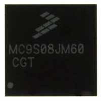
MC9S08JM60CGT Freescale Semiconductor, MC9S08JM60CGT Datasheet - Page 16

MC9S08JM60CGT
Manufacturer Part Number
MC9S08JM60CGT
Description
IC MCU 8BIT 60K FLASH 48-QFN
Manufacturer
Freescale Semiconductor
Series
HCS08r
Datasheet
1.MC9S08JM32CLD.pdf
(388 pages)
Specifications of MC9S08JM60CGT
Core Processor
HCS08
Core Size
8-Bit
Speed
48MHz
Connectivity
I²C, LIN, SCI, SPI, USB
Peripherals
LVD, POR, PWM, WDT
Number Of I /o
37
Program Memory Size
60KB (60K x 8)
Program Memory Type
FLASH
Ram Size
4K x 8
Voltage - Supply (vcc/vdd)
2.7 V ~ 5.5 V
Data Converters
A/D 8x12b
Oscillator Type
External
Operating Temperature
-40°C ~ 85°C
Package / Case
48-QFN
Processor Series
S08JM
Core
HCS08
Data Bus Width
8 bit
Data Ram Size
4 KB
Interface Type
SCI/SPI
Maximum Clock Frequency
24 MHz
Number Of Programmable I/os
37
Number Of Timers
8
Maximum Operating Temperature
+ 85 C
Mounting Style
SMD/SMT
3rd Party Development Tools
EWS08
Development Tools By Supplier
DEMOJM, DEMOJMSKT, DEMOFLEXISJMSD, DEMO9S08JM16
Minimum Operating Temperature
- 40 C
On-chip Adc
8-ch x 12-bit
Cpu Family
HCS08
Device Core Size
8b
Frequency (max)
24MHz
Total Internal Ram Size
4KB
# I/os (max)
37
Number Of Timers - General Purpose
8
Operating Supply Voltage (typ)
3.3/5V
Operating Supply Voltage (max)
5.5V
Operating Supply Voltage (min)
2.7V
Instruction Set Architecture
CISC
Operating Temp Range
-40C to 85C
Operating Temperature Classification
Industrial
Mounting
Surface Mount
Pin Count
48
Package Type
QFN EP
Package
48QFN EP
Family Name
HCS08
Maximum Speed
24 MHz
Operating Supply Voltage
3.3|5 V
For Use With
DEMOJM - KIT DEMO FOR JM MCU FAMILYDEMOJMSKT - BOARD DEMO S08JM CARD W/SOCKET
Lead Free Status / RoHS Status
Lead free / RoHS Compliant
Eeprom Size
-
Lead Free Status / Rohs Status
Lead free / RoHS Compliant
Available stocks
Company
Part Number
Manufacturer
Quantity
Price
- Current page: 16 of 388
- Download datasheet (5Mb)
15.5 Initialization/Application Information ..........................................................................................267
16.1 Introduction ...................................................................................................................................271
16.2 Signal Description .........................................................................................................................276
16.3 Register Definition ........................................................................................................................280
16.4 Functional Description ..................................................................................................................286
16.5 Reset Overview .............................................................................................................................292
16.6 Interrupts .......................................................................................................................................292
17.1 Introduction ...................................................................................................................................295
17.2 External Signal Description ..........................................................................................................300
16
15.4.5 SPI Clock Formats ..........................................................................................................259
15.4.6 SPI Baud Rate Generation ..............................................................................................261
15.4.7 Special Features ..............................................................................................................262
15.4.8 Error Conditions .............................................................................................................263
15.4.9 Low Power Mode Options ..............................................................................................264
15.4.10SPI Interrupts ..................................................................................................................265
15.5.1 SPI Module Initialization Example .................................................................................267
16.1.1 Features ...........................................................................................................................273
16.1.2 Modes of Operation ........................................................................................................273
16.1.3 Block Diagram ................................................................................................................274
16.2.1 Detailed Signal Descriptions ..........................................................................................276
16.3.1 TPM Status and Control Register (TPMxSC) ................................................................280
16.3.2 TPM-Counter Registers (TPMxCNTH:TPMxCNTL) ....................................................281
16.3.3 TPM Counter Modulo Registers (TPMxMODH:TPMxMODL) ....................................282
16.3.4 TPM Channel n Status and Control Register (TPMxCnSC) ..........................................283
16.3.5 TPM Channel Value Registers (TPMxCnVH:TPMxCnVL) ..........................................285
16.4.1 Counter ............................................................................................................................287
16.4.2 Channel Mode Selection .................................................................................................288
16.5.1 General ............................................................................................................................292
16.5.2 Description of Reset Operation .......................................................................................292
16.6.1 General ............................................................................................................................292
16.6.2 Description of Interrupt Operation .................................................................................292
17.1.1 Clocking Requirements ...................................................................................................295
17.1.2 Current Consumption in USB Suspend ..........................................................................295
17.1.3 3.3 V Regulator ...............................................................................................................295
17.1.4 Features ...........................................................................................................................298
17.1.5 Modes of Operation ........................................................................................................298
17.1.6 Block Diagram ................................................................................................................299
17.2.1 USBDP ............................................................................................................................300
17.2.2 USBDN ...........................................................................................................................300
Universal Serial Bus Device Controller (S08USBV1)
Timer/Pulse-Width Modulator (S08TPMV3)
MC9S08JM60 Series Data Sheet, Rev. 3
Chapter 16
Chapter 17
Freescale Semiconductor
Related parts for MC9S08JM60CGT
Image
Part Number
Description
Manufacturer
Datasheet
Request
R
Part Number:
Description:
Manufacturer:
Freescale Semiconductor, Inc
Datasheet:
Part Number:
Description:
Manufacturer:
Freescale Semiconductor, Inc
Datasheet:
Part Number:
Description:
Manufacturer:
Freescale Semiconductor, Inc
Datasheet:
Part Number:
Description:
Manufacturer:
Freescale Semiconductor, Inc
Datasheet:
Part Number:
Description:
Manufacturer:
Freescale Semiconductor, Inc
Datasheet:
Part Number:
Description:
Manufacturer:
Freescale Semiconductor, Inc
Datasheet:
Part Number:
Description:
Manufacturer:
Freescale Semiconductor, Inc
Datasheet:
Part Number:
Description:
Manufacturer:
Freescale Semiconductor, Inc
Datasheet:
Part Number:
Description:
Manufacturer:
Freescale Semiconductor, Inc
Datasheet:
Part Number:
Description:
Manufacturer:
Freescale Semiconductor, Inc
Datasheet:
Part Number:
Description:
Manufacturer:
Freescale Semiconductor, Inc
Datasheet:
Part Number:
Description:
Manufacturer:
Freescale Semiconductor, Inc
Datasheet:
Part Number:
Description:
Manufacturer:
Freescale Semiconductor, Inc
Datasheet:
Part Number:
Description:
Manufacturer:
Freescale Semiconductor, Inc
Datasheet:
Part Number:
Description:
Manufacturer:
Freescale Semiconductor, Inc
Datasheet:


