MC9S08DZ60ACLF Freescale Semiconductor, MC9S08DZ60ACLF Datasheet - Page 412
MC9S08DZ60ACLF
Manufacturer Part Number
MC9S08DZ60ACLF
Description
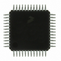
IC MCU 60K FLASH 4K RAM 48-LQFP
Manufacturer
Freescale Semiconductor
Series
HCS08r
Datasheets
1.DEMO9S08DZ60.pdf
(416 pages)
2.EVB9S08DZ60.pdf
(4 pages)
3.MC9S08DZ48AMLF.pdf
(458 pages)
Specifications of MC9S08DZ60ACLF
Core Processor
HCS08
Core Size
8-Bit
Speed
40MHz
Connectivity
CAN, I²C, LIN, SCI, SPI
Peripherals
LVD, POR, PWM, WDT
Number Of I /o
39
Program Memory Size
60KB (60K x 8)
Program Memory Type
FLASH
Eeprom Size
2K x 8
Ram Size
4K x 8
Voltage - Supply (vcc/vdd)
2.7 V ~ 5.5 V
Data Converters
A/D 16x12b
Oscillator Type
External
Operating Temperature
-40°C ~ 85°C
Package / Case
48-LQFP
Processor Series
S08DZ
Core
HCS08
Data Bus Width
8 bit
Data Ram Size
4 KB
Interface Type
CAN, I2C, SCI, SPI
Maximum Clock Frequency
40 MHz
Number Of Programmable I/os
53
Number Of Timers
2
Operating Supply Voltage
5.5 V
Maximum Operating Temperature
+ 85 C
Mounting Style
SMD/SMT
3rd Party Development Tools
EWS08
Development Tools By Supplier
DEMO9S08DZ60
Minimum Operating Temperature
- 40 C
On-chip Adc
12 bit, 24 Channel
For Use With
DEMO9S08DZ60 - BOARD DEMOEVB9S08DZ60 - BOARD EVAL FOR 9S08DZ60
Lead Free Status / RoHS Status
Lead free / RoHS Compliant
Available stocks
Company
Part Number
Manufacturer
Quantity
Price
Company:

Part Number:
MC9S08DZ60ACLF
Manufacturer:
FREESCAL
Quantity:
1 250
Company:
Part Number:
MC9S08DZ60ACLF
Manufacturer:
Freescale Semiconductor
Quantity:
10 000


Chapter 18 Debug Module (S08DBGV3) (128K)
18.4.4
The TBC is the main controller for the DBG module. Its function is to decide whether data should be stored
in the FIFO based on the trigger mode and the match signals from the comparator. The TBC also
determines whether a request to break the CPU should occur.
The TAG bit in DBGC controls whether CPU breakpoints are treated as tag-type or force-type breakpoints.
The TRGSEL bit in DBGT controls whether a comparator A or B match is further qualified by opcode
tracking logic. Each comparator has a separate circuit to track opcodes because the comparators could
correspond to separate instructions that could be propagating through the instruction queue at the same
time.
In end-type trace runs (BEGIN=0), when the comparator registers match, including the optional R/W
match, this signal goes to the CPU break logic where BRKEN determines whether a CPU break is
requested and the TAG control bit determines whether the CPU break will be a tag-type or force-type
breakpoint. When TRGSEL is set, the R/W qualified comparator match signal also passes through the
opcode tracking logic. If/when it propagates through this logic, it will cause a trigger to the ICE logic to
begin or end capturing information into the FIFO. In the case of an end-type (BEGIN=0) trace run, the
qualified comparator signal stops the FIFO from capturing any more information.
If a CPU breakpoint is also enabled, you would want TAG and TRGSEL to agree so that the CPU break
occurs at the same place in the application program as the FIFO stopped capturing information. If
TRGSEL was 0 and TAG was 1 in an end-type trace run, the FIFO would stop capturing as soon as the
comparator address matched, but the CPU would continue running until a TAG signal could propagate
through the CPUs instruction queue which could take a long time in the case where changes of flow caused
the instruction queue to be flushed. If TRGSEL was one and TAG was zero in an end-type trace run, the
CPU would break before the comparator match signal could propagate through the opcode tracking logic
to end the trace run.
In begin-type trace runs (BEGIN=1), the start of FIFO capturing is triggered by the qualified comparator
signals, and the CPU breakpoint (if enabled by BRKEN=1) is triggered when the FIFO becomes full. Since
this FIFO full condition does not correspond to the execution of a tagged instruction, it would not make
sense to use TAG=1 for a begin-type trace run.
18.4.4.1
The definition of begin- and end-trigger as used in the DBG module are as follows:
18.4.4.2
Arming occurs by enabling the DBG module by setting the DBGEN bit and by setting the ARM bit in the
DBGC register. The ARM bit in the DBGC register and the ARMF bit in the DBGS register are cleared
when the trigger condition is met in end-trigger mode or when the FIFO is filled in begin-trigger mode. In
the case of an end-trace where DBGEN=1 and BEGIN=0, ARM and ARMF are cleared by any reset to
412
•
•
Begin-trigger: Storage in FIFO occurs after the trigger and continues until 8 locations are filled.
End-trigger: Storage in FIFO occurs until the trigger with the least recent data falling out of the
FIFO if more than 8 words are collected.
Trigger Break Control (TBC)
Begin- and End-Trigger
Arming the DBG Module
MC9S08DZ128 Series Data Sheet, Rev. 1
Freescale Semiconductor
Related parts for MC9S08DZ60ACLF
Image
Part Number
Description
Manufacturer
Datasheet
Request
R

Part Number:
Description:
Manufacturer:
Freescale Semiconductor, Inc
Datasheet:
Part Number:
Description:
Manufacturer:
Freescale Semiconductor, Inc
Datasheet:
Part Number:
Description:
Manufacturer:
Freescale Semiconductor, Inc
Datasheet:
Part Number:
Description:
Manufacturer:
Freescale Semiconductor, Inc
Datasheet:
Part Number:
Description:
Manufacturer:
Freescale Semiconductor, Inc
Datasheet:
Part Number:
Description:
Manufacturer:
Freescale Semiconductor, Inc
Datasheet:
Part Number:
Description:
Manufacturer:
Freescale Semiconductor, Inc
Datasheet:
Part Number:
Description:
Manufacturer:
Freescale Semiconductor, Inc
Datasheet:
Part Number:
Description:
Manufacturer:
Freescale Semiconductor, Inc
Datasheet:
Part Number:
Description:
Manufacturer:
Freescale Semiconductor, Inc
Datasheet:
Part Number:
Description:
Manufacturer:
Freescale Semiconductor, Inc
Datasheet:
Part Number:
Description:
Manufacturer:
Freescale Semiconductor, Inc
Datasheet:
Part Number:
Description:
Manufacturer:
Freescale Semiconductor, Inc
Datasheet:
Part Number:
Description:
Manufacturer:
Freescale Semiconductor, Inc
Datasheet:
Part Number:
Description:
Manufacturer:
Freescale Semiconductor, Inc
Datasheet: