M37542F8FP#U0 Renesas Electronics America, M37542F8FP#U0 Datasheet - Page 114
M37542F8FP#U0
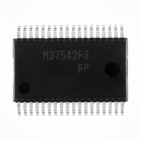
Manufacturer Part Number
M37542F8FP#U0
Description
IC 740 MCU FLASH 32K 36SSOP
Manufacturer
Renesas Electronics America
Series
740/38000r
Datasheet
1.M37542F8FPU0.pdf
(124 pages)
Specifications of M37542F8FP#U0
Core Processor
740
Core Size
8-Bit
Speed
8MHz
Connectivity
SIO, UART/USART
Peripherals
WDT
Number Of I /o
29
Program Memory Size
32KB (32K x 8)
Program Memory Type
FLASH
Ram Size
1K x 8
Voltage - Supply (vcc/vdd)
2.2 V ~ 5.5 V
Data Converters
A/D 8x10b
Oscillator Type
Internal
Operating Temperature
-20°C ~ 85°C
Package / Case
36-SSOP
Lead Free Status / RoHS Status
Lead free / RoHS Compliant
Eeprom Size
-
Available stocks
Company
Part Number
Manufacturer
Quantity
Price


7542 Group
Notes on Output Compare
1. When the selected source timer of each compare channel is
2. Do not write the same data to both of compare latch x0 (x=0, 1,
3. When setting value of the compare register is larger than timer
4. When the compare x trigger enable bit is cleared to “0” (dis-
Rev.3.03
REJ03B0006-0303
stopped, written data to compare register is loaded to the com-
pare latch simultaneously.
2, 3) and x1.
setting value, compare match signal is not generated. Accord-
ingly, the output waveform is fixed to “L” or “H” level.
However, when setting value of another compare register is
smaller than timer setting value, this compare match signal is
generated. Accordingly, if the corresponding compare latch y
(y=00, 01, 10, 11, 20, 21, 30, 31) interrupt source bit is set to “1”
(valid), compare match interrupt request occurs.
abled), the match trigger to the waveform output circuit is
disabled. Accordingly, the output waveform can be fixed to “L”
or “H” level.
However, in this case, the compare match signal is generated.
Accordingly, if the corresponding compare latch y (y=00, 01, 10,
11, 20, 21, 30, 31) interrupt source bit is set to “1”
(valid),compare match interrupt request occurs.
Jul 11, 2008
Page 112 of 117
Notes on Input Capture
1. If the capture trigger is input while the capture register (low-or-
2. Timer A cannot be used for the capture source timer in the fol-
3. As shown below, when the capture input is performed to both
• When “1” is written to capture latch 00 software trigger bit (bit 0
• When external trigger of capture latch 00 and software trigger of
• When external trigger of capture latch 01 and software trigger of
4. When the capture interrupt is used as the interrupt for return
of capture software trigger register (address 13
latch 01 software trigger bit (bit 1 of capture software trigger reg-
ister) at the same time
capture latch 01 occur at the same time
capture latch 00 occur at the same time
der and high-order) is in read, captured value is changed
between high-order reading and low-order reading. Accordingly,
some countermeasure by software is recommended, for ex-
ample comparing the values that twice of read.
Timer B cannot be used for the capture source timer in the fol-
lowing state;
capture latch 00 and 01 at the same time, the value of capture
0 status bit (bit 4 of capture/compare status register (address
22
from stop mode, set the capture 0 noise filter clock selection
bits (bits 5 and 4 of capture mode register (address 20
“00 (Filter stop)” (same as capture 1).
lowing state;
• X
• Timer A count source: On-chip oscillator output.
• X
• Timer B count source: Timer A underflow
• Timer A count source: On-chip oscillator output.
(bits 7 and 6 of CPU mode register (address 3B
16
IN
IN
)) is undefined (same as capture 1).
oscillation selected by clock division ratio selection bits
oscillation selected by clock division ratio selection bits
16
)) and capture
16
))
16
)) to
Related parts for M37542F8FP#U0
Image
Part Number
Description
Manufacturer
Datasheet
Request
R

Part Number:
Description:
KIT STARTER FOR M16C/29
Manufacturer:
Renesas Electronics America
Datasheet:

Part Number:
Description:
KIT STARTER FOR R8C/2D
Manufacturer:
Renesas Electronics America
Datasheet:

Part Number:
Description:
R0K33062P STARTER KIT
Manufacturer:
Renesas Electronics America
Datasheet:

Part Number:
Description:
KIT STARTER FOR R8C/23 E8A
Manufacturer:
Renesas Electronics America
Datasheet:

Part Number:
Description:
KIT STARTER FOR R8C/25
Manufacturer:
Renesas Electronics America
Datasheet:

Part Number:
Description:
KIT STARTER H8S2456 SHARPE DSPLY
Manufacturer:
Renesas Electronics America
Datasheet:

Part Number:
Description:
KIT STARTER FOR R8C38C
Manufacturer:
Renesas Electronics America
Datasheet:

Part Number:
Description:
KIT STARTER FOR R8C35C
Manufacturer:
Renesas Electronics America
Datasheet:

Part Number:
Description:
KIT STARTER FOR R8CL3AC+LCD APPS
Manufacturer:
Renesas Electronics America
Datasheet:
Part Number:
Description:
KIT STARTER FOR RX610
Manufacturer:
Renesas Electronics America
Datasheet:

Part Number:
Description:
KIT STARTER FOR R32C/118
Manufacturer:
Renesas Electronics America
Datasheet:

Part Number:
Description:
KIT DEV RSK-R8C/26-29
Manufacturer:
Renesas Electronics America
Datasheet:

Part Number:
Description:
KIT STARTER FOR SH7124
Manufacturer:
Renesas Electronics America
Datasheet:

Part Number:
Description:
KIT STARTER FOR H8SX/1622
Manufacturer:
Renesas Electronics America
Datasheet:

Part Number:
Description:
KIT DEV FOR SH7203
Manufacturer:
Renesas Electronics America
Datasheet: