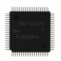
HD64F38024DV Renesas Electronics America, HD64F38024DV Datasheet - Page 138

HD64F38024DV
Manufacturer Part Number
HD64F38024DV
Description
IC H8/SLP MCU FLASH 80QFP
Manufacturer
Renesas Electronics America
Series
H8® H8/300L SLPr
Datasheets
1.US38024-BAG1.pdf
(684 pages)
2.DF36012GFYV.pdf
(1021 pages)
3.DF38102HV.pdf
(145 pages)
Specifications of HD64F38024DV
Core Processor
H8/300L
Core Size
8-Bit
Speed
10MHz
Connectivity
SCI
Peripherals
LCD, PWM, WDT
Number Of I /o
51
Program Memory Size
32KB (32K x 8)
Program Memory Type
FLASH
Ram Size
1K x 8
Voltage - Supply (vcc/vdd)
1.8 V ~ 5.5 V
Data Converters
A/D 8x10b
Oscillator Type
Internal
Operating Temperature
-40°C ~ 85°C
Package / Case
80-QFP
Lead Free Status / RoHS Status
Lead free / RoHS Compliant
Eeprom Size
-
Available stocks
Company
Part Number
Manufacturer
Quantity
Price
Company:
Part Number:
HD64F38024DV
Manufacturer:
Renesas Electronics America
Quantity:
10 000
Section 3 CPU Operation States
3.2.3
A reset has the highest priority of all exception handling. After the RES pin goes to low level
putting the CPU in reset state, the RES pin is then put at high level, and reset exception handling is
started at the point when the reset conditions are met. For details on reset conditions refer to the
applicable hardware manual. When reset exception handling is started, the CPU gets a start
address from the exception handling vector table, and starts executing the exception handling
routine from that address. During execution of this routine and immediately after, all interrupts
including NMI are masked.
When interrupt exception handling is started, the CPU refers to the stack pointer (R7) and pushes
the PC and CCR contents to the stack. The CCR I bit is then set to 1, a start address is acquired
from the exception handling vector table, and the interrupt exception handling routine is executed
from this address. The stack state in this case is as shown in figure 3-4.
Rev. 2.00 Dec 27, 2004 page 124 of 128
REJ09B0214-0200
SP – 4
SP – 3
SP – 2
SP – 1
SP (R7)
Notation
PC
PC
CCR:
SP:
Notes:
Figure 3-4 Stack State after Completion of Interrupt Exception Handling
Outline of Exception Handling Operation
H
L
:
:
Upper 8 bits of program counter (PC)
Lower 8 bits of program counter (PC)
Condition code register
Stack pointer
1.
2.
* Ignored on return from interrupt
Prior to start of interrupt
Saving and restoring of register contents must always be done
in word size, and must start from an even-numbered address.
PC shows the address of the first instruction to be executed upon
return from the interrupt.
exception handling
Stack
saved to stack
Contents
SP (R7)
SP + 1
SP + 2
SP + 3
SP + 4
After completion of interrupt
exception handling
CCR*
CCR
PC
PC
H
L
Even-numbered
address


