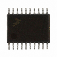
MC9S08EL16CTJ Freescale Semiconductor, MC9S08EL16CTJ Datasheet - Page 212

MC9S08EL16CTJ
Manufacturer Part Number
MC9S08EL16CTJ
Description
MCU 16KB FLASH SLIC 20TSSOP
Manufacturer
Freescale Semiconductor
Series
HCS08r
Datasheet
1.DEMO9S08EL32.pdf
(356 pages)
Specifications of MC9S08EL16CTJ
Core Processor
HCS08
Core Size
8-Bit
Speed
40MHz
Connectivity
I²C, LIN, SCI, SPI
Peripherals
LVD, POR, PWM, WDT
Number Of I /o
16
Program Memory Size
16KB (16K x 8)
Program Memory Type
FLASH
Eeprom Size
512 x 8
Ram Size
1K x 8
Voltage - Supply (vcc/vdd)
2.7 V ~ 5.5 V
Data Converters
A/D 12x10b
Oscillator Type
External
Operating Temperature
-40°C ~ 85°C
Package / Case
20-TSSOP
Processor Series
S08EL
Core
HCS08
Data Bus Width
8 bit
Data Ram Size
1 KB
Interface Type
SCI, SPI, I2C, SLIC
Maximum Clock Frequency
200 KHz
Number Of Programmable I/os
16
Number Of Timers
2
Operating Supply Voltage
5.5 V
Maximum Operating Temperature
+ 85 C
Mounting Style
SMD/SMT
3rd Party Development Tools
EWS08
Development Tools By Supplier
DEMO9S08EL32AUTO, DEMO9S08EL32
Minimum Operating Temperature
- 40 C
On-chip Adc
10 bit, 12 Channel
For Use With
DEMO9S08EL32 - BOARD DEMO FOR 9S08 EL MCUDEMO9S08EL32AUTO - DEMO BOARD EL32 AUTO
Lead Free Status / RoHS Status
Lead free / RoHS Compliant
- Current page: 212 of 356
- Download datasheet (9Mb)
unmasked, after 8 bytes are received or an error is detected. At this interrupt, the SLCSV will indicate an
error condition (in case of byte framing error, idle bus) or that the receive buffer is full. If the data is
successfully received, the user must then empty the buffer by reading SLCD7-SLCD0 and then subtract 8
from the software byte count. When this software counter reaches 8 or fewer, the remaining data bytes will
fit in the buffer and only one interrupt should occur. At this time, the final interrupt may be handled
normally, continuing to use the software counter to read the proper number of bytes from the appropriate
SLCD registers.
12.6.8.3
Possible errors on command message data are:
12.6.9
Figure 12-16
master node.
Request message frames refer to LIN messages frames where the master node is “requesting” the slave
node to supply information. The implication is that the slave will then be transmitting data to the master
for this message frame. This can be a standard LIN message frame of 1–8 data bytes, a reserved LIN
system message (using 0x3D identifier), or an extended request message frame utilizing the reserved 0x3E
identifier or perhaps the 0x3F LIN reserved extended identifier. The SLIC module is capable of handling
request message frames containing up to 64 bytes of data, while still automatically calculating and/or
verifying the checksum.
12.6.9.1
Dealing with request messages with the SLIC is very similar to dealing with command messages, with one
important difference. Because the SLIC is now to be transmitting data in the LIN message frame, the user
software must load the data to be transmitted into the message buffer prior to initiating the transmission.
214
•
•
•
•
Byte Framing Error
Checksum-Error (LIN specified error)
No-Bus-Activity (LIN specified error)
Receiver Buffer Overrun Error
Handling Request LIN Message Frames
Possible Errors on Command Message Data
shows how to handle request message frames, where the SLIC module is sending data to the
Standard Request Message Frames
Do not write SLCDLC more than one time per LIN message frame. The
SLIC tracks the number of sent or received bytes based on the value written
to this register at the beginning of the data field and rewriting this register
will corrupt the checksum calculation and cause unpredictable behavior in
the SLIC module. The application software must track the number of sent
or received bytes to know what the current byte count in the SLIC is. If
programming in C, make sure to use the VOLATILE modifier on this
variable (or make it a global variable) to ensure that it keeps its value
between interrupts.
MC9S08EL32 Series and MC9S08SL16 Series Data Sheet, Rev. 3
NOTE
Freescale Semiconductor
Related parts for MC9S08EL16CTJ
Image
Part Number
Description
Manufacturer
Datasheet
Request
R
Part Number:
Description:
Manufacturer:
Freescale Semiconductor, Inc
Datasheet:
Part Number:
Description:
Manufacturer:
Freescale Semiconductor, Inc
Datasheet:
Part Number:
Description:
Manufacturer:
Freescale Semiconductor, Inc
Datasheet:
Part Number:
Description:
Manufacturer:
Freescale Semiconductor, Inc
Datasheet:
Part Number:
Description:
Manufacturer:
Freescale Semiconductor, Inc
Datasheet:
Part Number:
Description:
Manufacturer:
Freescale Semiconductor, Inc
Datasheet:
Part Number:
Description:
Manufacturer:
Freescale Semiconductor, Inc
Datasheet:
Part Number:
Description:
Manufacturer:
Freescale Semiconductor, Inc
Datasheet:
Part Number:
Description:
Manufacturer:
Freescale Semiconductor, Inc
Datasheet:
Part Number:
Description:
Manufacturer:
Freescale Semiconductor, Inc
Datasheet:
Part Number:
Description:
Manufacturer:
Freescale Semiconductor, Inc
Datasheet:
Part Number:
Description:
Manufacturer:
Freescale Semiconductor, Inc
Datasheet:
Part Number:
Description:
Manufacturer:
Freescale Semiconductor, Inc
Datasheet:
Part Number:
Description:
Manufacturer:
Freescale Semiconductor, Inc
Datasheet:
Part Number:
Description:
Manufacturer:
Freescale Semiconductor, Inc
Datasheet:


