ATXMEGA16A4-CUR Atmel, ATXMEGA16A4-CUR Datasheet - Page 354
ATXMEGA16A4-CUR
Manufacturer Part Number
ATXMEGA16A4-CUR
Description
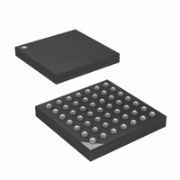
MCU AVR 16+4KB FLASH 49VFBGA
Manufacturer
Atmel
Series
AVR® XMEGAr
Specifications of ATXMEGA16A4-CUR
Core Processor
AVR
Core Size
8/16-Bit
Speed
32MHz
Connectivity
I²C, IrDA, SPI, UART/USART
Peripherals
Brown-out Detect/Reset, DMA, POR, PWM, WDT
Number Of I /o
34
Program Memory Size
16KB (8K x 16)
Program Memory Type
FLASH
Eeprom Size
1K x 8
Ram Size
2K x 8
Voltage - Supply (vcc/vdd)
1.6 V ~ 3.6 V
Data Converters
A/D 12x12b, D/A 2x12b
Oscillator Type
Internal
Operating Temperature
-40°C ~ 85°C
Package / Case
49-VFBGA
For Use With
ATAVRONEKIT - KIT AVR/AVR32 DEBUGGER/PROGRMMRATSTK600 - DEV KIT FOR AVR/AVR32770-1007 - ISP 4PORT ATMEL AVR MCU SPI/JTAG770-1004 - ISP 4PORT FOR ATMEL AVR MCU SPI
Lead Free Status / RoHS Status
Lead free / RoHS Compliant
Available stocks
Company
Part Number
Manufacturer
Quantity
Price


29.5.3
29.5.4
29.5.5
29.5.6
29.5.6.1
8077H–AVR–12/09
NVM Programming Key
Exception handling
Reset signalling
Instruction Set
LDS - Load data from PDIBUS Data Space using direct addressing
The key that must be sent using the KEY instruction is 64 bits long. The key that will enable
NVM Programming is:
0x1289AB45CDD888FF
There are several situations that are considered exceptions from normal operation. The excep-
tions depends on whether the PDI is in RX - or TX mode, and whether PDI or JTAG mode is
used.
While the PDI is in RX mode, these exceptions are defined as:
While the PDI is in TX mode, these exceptions are defined:
All exceptions are signalized to the PDI Controller. All on-going operations are then aborted and
the PDI is put in the ERROR state. The PDI will remain in this state until a BREAK is sent from
the External Programmer, and this will bring the PDI back to its default RX state.
Due to this mechanism the programmer can always synchronize the protocol by transmitting two
successive BREAK characters.
Through the Reset Register, the programmer can issue a reset and force the device into reset.
After clearing the Reset Register, reset is released unless some other reset source is active.
The PDI has a small instructions set that is used for all access to the PDI itself and to the internal
interfaces.All instructions are byte instructions. Most of the instructions require a number of byte
operands following the instruction. The instructions allow to external programmer to access the
PDI Controller, the NVM Controller and the NVM memories.
The LDS instruction is used to load data from the PDIBUS Data Space for serial read-out. The
LDS instruction is based on direct addressing, which means that the address must be given as
an argument to the instruction. Even though the protocol is based on byte-wise communication,
the LDS instruction supports multiple-bytes address - and data access. Four different
• PDI:
• JTAG:
• PDI:
• JTAG:
– The physical layer detects a parity error.
– The physical layer detects a frame error.
– The physical layer recognizes a BREAK character (also detected as a frame error).
– The physical layer detects a parity error.
– The physical layer recognizes a BREAK character (also detected as a parity error).
– The physical layer detects a data collision.
– The physical layer detects a parity error (on the dummy data shifted in on TDI).
– The physical layer recognizes a BREAK character.
XMEGA A
354
Related parts for ATXMEGA16A4-CUR
Image
Part Number
Description
Manufacturer
Datasheet
Request
R

Part Number:
Description:
DEV KIT FOR AVR/AVR32
Manufacturer:
Atmel
Datasheet:

Part Number:
Description:
INTERVAL AND WIPE/WASH WIPER CONTROL IC WITH DELAY
Manufacturer:
ATMEL Corporation
Datasheet:
Part Number:
Description:
Low-Voltage Voice-Switched IC for Hands-Free Operation
Manufacturer:
ATMEL Corporation
Datasheet:
Part Number:
Description:
MONOLITHIC INTEGRATED FEATUREPHONE CIRCUIT
Manufacturer:
ATMEL Corporation
Datasheet:
Part Number:
Description:
AM-FM Receiver IC U4255BM-M
Manufacturer:
ATMEL Corporation
Datasheet:
Part Number:
Description:
Monolithic Integrated Feature Phone Circuit
Manufacturer:
ATMEL Corporation
Datasheet:
Part Number:
Description:
Multistandard Video-IF and Quasi Parallel Sound Processing
Manufacturer:
ATMEL Corporation
Datasheet:
Part Number:
Description:
High-performance EE PLD
Manufacturer:
ATMEL Corporation
Datasheet:
Part Number:
Description:
8-bit Flash Microcontroller
Manufacturer:
ATMEL Corporation
Datasheet:
Part Number:
Description:
2-Wire Serial EEPROM
Manufacturer:
ATMEL Corporation
Datasheet: