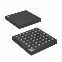
ATXMEGA16A4-CUR Atmel, ATXMEGA16A4-CUR Datasheet - Page 374

ATXMEGA16A4-CUR
Manufacturer Part Number
ATXMEGA16A4-CUR
Description
MCU AVR 16+4KB FLASH 49VFBGA
Manufacturer
Atmel
Series
AVR® XMEGAr
Specifications of ATXMEGA16A4-CUR
Core Processor
AVR
Core Size
8/16-Bit
Speed
32MHz
Connectivity
I²C, IrDA, SPI, UART/USART
Peripherals
Brown-out Detect/Reset, DMA, POR, PWM, WDT
Number Of I /o
34
Program Memory Size
16KB (8K x 16)
Program Memory Type
FLASH
Eeprom Size
1K x 8
Ram Size
2K x 8
Voltage - Supply (vcc/vdd)
1.6 V ~ 3.6 V
Data Converters
A/D 12x12b, D/A 2x12b
Oscillator Type
Internal
Operating Temperature
-40°C ~ 85°C
Package / Case
49-VFBGA
For Use With
ATAVRONEKIT - KIT AVR/AVR32 DEBUGGER/PROGRMMRATSTK600 - DEV KIT FOR AVR/AVR32770-1007 - ISP 4PORT ATMEL AVR MCU SPI/JTAG770-1004 - ISP 4PORT FOR ATMEL AVR MCU SPI
Lead Free Status / RoHS Status
Lead free / RoHS Compliant
Available stocks
Company
Part Number
Manufacturer
Quantity
Price
- Current page: 374 of 445
- Download datasheet (6Mb)
30.11.2.14
30.11.3
Table 30-3.
30.11.3.1
30.11.3.2
8077H–AVR–12/09
CMD[6:0]
0x00
Fuses and Lock Bits
0x07
0x08
NVM Fuse and Lock Bit Commands
Group Configuration
NO_OPERATION
READ_FUSES
WRITE_LOCK_BITS
Read User Signature Row / Calibration Row
Write Lock Bits Write
Read Fuses
Fuse and Lock Bit Commands
The Read User Signature Row and Red Calibration Row commands are used to read one byte
from the User Signature Row or Calibration Row.
The destination register will be loaded during the execution of the LPM instruction.
The NVM Flash commands that can be used for accessing the Fuses and Lock Bits are listed in
Table
For self-programming of the Fuses and Lock Bits, the Trigger for Action Triggered Commands is
to set the CMDEX bit in the NVM CTRLA register (CMDEX). The Read Triggered Commands
are triggered by executing the (E)LPM instruction (LPM). The Write Triggered Commands is trig-
gered by a executing the SPM instruction (SPM).
The Change Protected column indicate if the trigger is protected by the Configuration Change
Protection (CCP) during self-programming. The two last columns shows the address pointer
used for addressing, and the source/destination data register.
Section 30.11.3.1 on page 374
algorithm for each NVM operation.
The Write Lock Bits command is used to program the Boot Lock Bits to a more secure settings
from software.
1.
2.
3.
during self-programming.
The BUSY flag in the NVM STATUS register will be set until the command is finished. The CPU
is halted during the complete execution of the command.
This command can be executed from both the Boot Loader Section and the Application Section.
The EEPROM and Flash Page Buffer is automatically erased when the Lock Bits are written.
The Read Fuses command is used to read the Fuses from software.
1. Load the Z-pointer with the byte address to read.
2. Load the NVM CMD register with the Read User Signature Row / Calibration Row
3. Execute the LPM instruction.
command
Load the NVM DATA0 register with the new Lock bit value.
Load the NVM CMD register with the Write Lock Bit command.
Set the CMDEX bit in the NVM CTRLA register. This requires the timed CCP sequence
30-3.
Description
No Operation
Read Fuses
Write Lock Bits
through
Trigger
CMDEX
CMDEX
-
Section 30.11.3.2 on page 374
CPU
Halted
N
N
-
Change
Protected
N
Y
-
Address
pointer
ADDR
ADDR
-
explain in details the
XMEGA A
Data
register
DATA
-
-
NVM
Busy
Y
Y
-
374
Related parts for ATXMEGA16A4-CUR
Image
Part Number
Description
Manufacturer
Datasheet
Request
R

Part Number:
Description:
DEV KIT FOR AVR/AVR32
Manufacturer:
Atmel
Datasheet:

Part Number:
Description:
INTERVAL AND WIPE/WASH WIPER CONTROL IC WITH DELAY
Manufacturer:
ATMEL Corporation
Datasheet:

Part Number:
Description:
Low-Voltage Voice-Switched IC for Hands-Free Operation
Manufacturer:
ATMEL Corporation
Datasheet:

Part Number:
Description:
MONOLITHIC INTEGRATED FEATUREPHONE CIRCUIT
Manufacturer:
ATMEL Corporation
Datasheet:

Part Number:
Description:
AM-FM Receiver IC U4255BM-M
Manufacturer:
ATMEL Corporation
Datasheet:

Part Number:
Description:
Monolithic Integrated Feature Phone Circuit
Manufacturer:
ATMEL Corporation
Datasheet:

Part Number:
Description:
Multistandard Video-IF and Quasi Parallel Sound Processing
Manufacturer:
ATMEL Corporation
Datasheet:

Part Number:
Description:
High-performance EE PLD
Manufacturer:
ATMEL Corporation
Datasheet:

Part Number:
Description:
8-bit Flash Microcontroller
Manufacturer:
ATMEL Corporation
Datasheet:

Part Number:
Description:
2-Wire Serial EEPROM
Manufacturer:
ATMEL Corporation
Datasheet:


