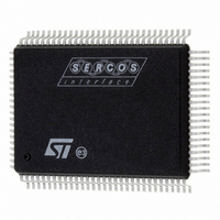
ST92F150CV1QB STMicroelectronics, ST92F150CV1QB Datasheet - Page 162

ST92F150CV1QB
Manufacturer Part Number
ST92F150CV1QB
Description
MCU 8BIT 128K FLASH 100PQFP
Manufacturer
STMicroelectronics
Series
ST9r
Datasheet
1.ST92F150CV1TB.pdf
(429 pages)
Specifications of ST92F150CV1QB
Core Processor
ST9
Core Size
8/16-Bit
Speed
24MHz
Connectivity
CAN, I²C, LIN, SCI, SPI
Peripherals
DMA, LVD, POR, PWM, WDT
Number Of I /o
77
Program Memory Size
128KB (128K x 8)
Program Memory Type
FLASH
Eeprom Size
1K x 8
Ram Size
4K x 8
Voltage - Supply (vcc/vdd)
4.5 V ~ 5.5 V
Data Converters
A/D 16x10b
Oscillator Type
Internal
Operating Temperature
-40°C ~ 105°C
Package / Case
100-QFP
Processor Series
ST92F15x
Core
ST9
Data Bus Width
8 bit, 16 bit
Data Ram Size
6 KB
Interface Type
CAN, I2C, SCI, SPI
Maximum Clock Frequency
24 MHz
Number Of Programmable I/os
80
Number Of Timers
5 x 16 bit
Operating Supply Voltage
4.5 V to 5.5 V
Maximum Operating Temperature
+ 105 C
Mounting Style
SMD/SMT
Development Tools By Supplier
ST92F150-EPB
Minimum Operating Temperature
- 40 C
On-chip Adc
16 bit x 10 bit
Lead Free Status / RoHS Status
Lead free / RoHS Compliant
Other names
497-4882
Available stocks
Company
Part Number
Manufacturer
Quantity
Price
Company:
Part Number:
ST92F150CV1QB
Manufacturer:
STMicroelectronics
Quantity:
10 000
- Current page: 162 of 429
- Download datasheet (8Mb)
TIMER/WATCHDOG (WDT)
TIMER/WATCHDOG (Cont’d)
10.1.5 Register Description
The Timer/Watchdog is associated with 4 registers
mapped into Group F, Page 0 of the Register File.
WDTHR: Timer/Watchdog High Register
WDTLR: Timer/Watchdog Low Register
WDTPR: Timer/Watchdog Prescaler Register
WDTCR: Timer/Watchdog Control Register
Three additional control bits are mapped in the fol-
lowing registers on Page 0:
Watchdog Mode Enable, (WCR.6)
Top Level Interrupt Selection, (EIVR.2)
Interrupt A0 Channel Selection, (EIVR.1)
Note: The registers containing these bits also con-
tain other functions. Only the bits relevant to the
operation of the Timer/Watchdog are shown here.
Counter Register
This 16-bit register (WDTLR, WDTHR) is used to
load the 16-bit counter value. The registers can be
read or written “on the fly”.
TIMER/WATCHDOG HIGH REGISTER (WDTHR)
R248 - Read/Write
Register Page: 0
Reset value: 1111 1111 (FFh)
Bits 7:0 = R[15:8] Counter Most Significant Bits.
TIMER/WATCHDOG LOW REGISTER (WDTLR)
R249 - Read/Write
Register Page: 0
Reset value: 1111 1111b (FFh)
Bits 7:0 = R[7:0] Counter Least Significant Bits.
162/429
9
R15
R7
7
7
R14
R6
R13
R5
R12
R4
R11
R3
R10
R2
R9
R1
R8
R0
0
0
TIMER/WATCHDOG PRESCALER REGISTER
(WDTPR)
R250 - Read/Write
Register Page: 0
Reset value: 1111 1111 (FFh)
Bits 7:0 = PR[7:0] Prescaler value.
A programmable value from 1 (00h) to 256 (FFh).
Warning: In order to prevent incorrect operation of
the Timer/Watchdog, the prescaler (WDTPR) and
counter (WDTRL, WDTRH) registers must be ini-
tialised before starting the Timer/Watchdog. If this
is not done, counting will start with the reset (un-in-
itialised) values.
WATCHDOG TIMER CONTROL REGISTER
(WDTCR)
R251- Read/Write
Register Page: 0
Reset value: 0001 0010 (12h)
Bit 7 = ST_SP: Start/Stop Bit.
This bit is set and cleared by software.
0: Stop counting
1: Start counting (see Warning above)
Bit 6 = S_C: Single/Continuous.
This bit is set and cleared by software.
0: Continuous Mode
1: Single Mode
Bits 5:4 = INMD[1:2]: Input mode selection bits.
These bits select the input mode:
ST_SP
PR7
INMD1
7
7
0
0
1
1
S_C
PR6
INMD2
INMD1
PR5
0
1
0
1
INMD2
PR4
Gated Input (Reset value)
INEN
PR3
Retriggerable Input
Triggerable Input
Event Counter
INPUT MODE
OUTMD
PR2
WROUT
PR1
OUTEN
PR0
0
0
Related parts for ST92F150CV1QB
Image
Part Number
Description
Manufacturer
Datasheet
Request
R

Part Number:
Description:
BOARD PROGRAM FOR ST92F150 MCU
Manufacturer:
STMicroelectronics
Datasheet:

Part Number:
Description:
BOARD EVALUATION FOR ST9 SERIES
Manufacturer:
STMicroelectronics
Datasheet:

Part Number:
Description:
BOARD EMULATOR FOR ST9 SERIES
Manufacturer:
STMicroelectronics
Datasheet:

Part Number:
Description:
MCU, MPU & DSP Development Tools ST9 Dedication Board
Manufacturer:
STMicroelectronics
Datasheet:

Part Number:
Description:
STMicroelectronics [RIPPLE-CARRY BINARY COUNTER/DIVIDERS]
Manufacturer:
STMicroelectronics
Datasheet:

Part Number:
Description:
STMicroelectronics [LIQUID-CRYSTAL DISPLAY DRIVERS]
Manufacturer:
STMicroelectronics
Datasheet:

Part Number:
Description:
BOARD EVAL FOR MEMS SENSORS
Manufacturer:
STMicroelectronics
Datasheet:

Part Number:
Description:
NPN TRANSISTOR POWER MODULE
Manufacturer:
STMicroelectronics
Datasheet:

Part Number:
Description:
TURBOSWITCH ULTRA-FAST HIGH VOLTAGE DIODE
Manufacturer:
STMicroelectronics
Datasheet:

Part Number:
Description:
Manufacturer:
STMicroelectronics
Datasheet:

Part Number:
Description:
DIODE / SCR MODULE
Manufacturer:
STMicroelectronics
Datasheet:

Part Number:
Description:
DIODE / SCR MODULE
Manufacturer:
STMicroelectronics
Datasheet:


