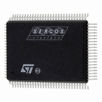
ST92F150CV1QB STMicroelectronics, ST92F150CV1QB Datasheet - Page 98

ST92F150CV1QB
Manufacturer Part Number
ST92F150CV1QB
Description
MCU 8BIT 128K FLASH 100PQFP
Manufacturer
STMicroelectronics
Series
ST9r
Datasheet
1.ST92F150CV1TB.pdf
(429 pages)
Specifications of ST92F150CV1QB
Core Processor
ST9
Core Size
8/16-Bit
Speed
24MHz
Connectivity
CAN, I²C, LIN, SCI, SPI
Peripherals
DMA, LVD, POR, PWM, WDT
Number Of I /o
77
Program Memory Size
128KB (128K x 8)
Program Memory Type
FLASH
Eeprom Size
1K x 8
Ram Size
4K x 8
Voltage - Supply (vcc/vdd)
4.5 V ~ 5.5 V
Data Converters
A/D 16x10b
Oscillator Type
Internal
Operating Temperature
-40°C ~ 105°C
Package / Case
100-QFP
Processor Series
ST92F15x
Core
ST9
Data Bus Width
8 bit, 16 bit
Data Ram Size
6 KB
Interface Type
CAN, I2C, SCI, SPI
Maximum Clock Frequency
24 MHz
Number Of Programmable I/os
80
Number Of Timers
5 x 16 bit
Operating Supply Voltage
4.5 V to 5.5 V
Maximum Operating Temperature
+ 105 C
Mounting Style
SMD/SMT
Development Tools By Supplier
ST92F150-EPB
Minimum Operating Temperature
- 40 C
On-chip Adc
16 bit x 10 bit
Lead Free Status / RoHS Status
Lead free / RoHS Compliant
Other names
497-4882
Available stocks
Company
Part Number
Manufacturer
Quantity
Price
Company:
Part Number:
ST92F150CV1QB
Manufacturer:
STMicroelectronics
Quantity:
10 000
- Current page: 98 of 429
- Download datasheet (8Mb)
ST92F124/F150/F250 - INTERRUPTS
ARBITRATION MODES (Cont’d)
5.5.2 Nested Mode
The difference between Nested mode and Con-
current mode, lies in the modification of the Cur-
rent Priority Level (CPL) during interrupt process-
ing.
The arbitration phase is basically identical to Con-
current mode, however, once the request is ac-
knowledged, the CPL is saved in the Nested Inter-
rupt Control Register (NICR) by setting the NICR
bit corresponding to the CPL value (i.e. if the CPL
is 3, the bit 3 will be set).
The CPL is then loaded with the priority of the re-
quest just acknowledged; the next arbitration cycle
is thus performed with reference to the priority of
the interrupt service routine currently being exe-
cuted.
Start of Interrupt Routine
The interrupt cycle performs the following steps:
Figure 48. Simple Example of a Sequence of Interrupt Requests with:
- Nested mode
- IEN unchanged by the interrupt routines
98/429
9
0
1
2
3
4
5
6
7
Priority Level of
Interrupt Request
CPL is set to 7
INT5
MAIN
ei
CPL=5
INT 5
INT2
INT3
INT4
CPL=2
INT 2
INT0
CPL=0
INT 0
CPL2 < CPL4:
Serviced next
CPL=3
INT 3
INT6
CPL6 > CPL3:
INT6 pending
CPL=4
– All maskable interrupt requests are disabled by
– CPL is saved in the special NICR stack to hold
– Priority level of the acknowledged routine is
– The PC low byte is pushed onto system stack.
– The PC high byte is pushed onto system stack.
– If ENCSR is set, CSR is pushed onto system
– The Flag register is pushed onto system stack.
– The PC is loaded with the 16-bit vector stored in
– If ENCSR is set, CSR is loaded with ISR con-
INT 4
INT2
clearing CICR.IEN.
the priority level of the suspended routine.
stored in CPL, so that the next request priority
will be compared with the one of the routine cur-
rently being serviced.
stack.
the Vector Table, pointed to by the IVR.
tents; otherwise ISR is used in place of CSR until
iret instruction.
CPL=2
INT 2
INTERRUPT 0 HAS PRIORITY LEVEL 0
INTERRUPT 2 HAS PRIORITY LEVEL 2
INTERRUPT 3 HAS PRIORITY LEVEL 3
INTERRUPT 4 HAS PRIORITY LEVEL 4
INTERRUPT 5 HAS PRIORITY LEVEL 5
INTERRUPT 6 HAS PRIORITY LEVEL 6
CPL=6
INT 6
CPL=7
MAIN
Related parts for ST92F150CV1QB
Image
Part Number
Description
Manufacturer
Datasheet
Request
R

Part Number:
Description:
BOARD PROGRAM FOR ST92F150 MCU
Manufacturer:
STMicroelectronics
Datasheet:

Part Number:
Description:
BOARD EVALUATION FOR ST9 SERIES
Manufacturer:
STMicroelectronics
Datasheet:

Part Number:
Description:
BOARD EMULATOR FOR ST9 SERIES
Manufacturer:
STMicroelectronics
Datasheet:

Part Number:
Description:
MCU, MPU & DSP Development Tools ST9 Dedication Board
Manufacturer:
STMicroelectronics
Datasheet:

Part Number:
Description:
STMicroelectronics [RIPPLE-CARRY BINARY COUNTER/DIVIDERS]
Manufacturer:
STMicroelectronics
Datasheet:

Part Number:
Description:
STMicroelectronics [LIQUID-CRYSTAL DISPLAY DRIVERS]
Manufacturer:
STMicroelectronics
Datasheet:

Part Number:
Description:
BOARD EVAL FOR MEMS SENSORS
Manufacturer:
STMicroelectronics
Datasheet:

Part Number:
Description:
NPN TRANSISTOR POWER MODULE
Manufacturer:
STMicroelectronics
Datasheet:

Part Number:
Description:
TURBOSWITCH ULTRA-FAST HIGH VOLTAGE DIODE
Manufacturer:
STMicroelectronics
Datasheet:

Part Number:
Description:
Manufacturer:
STMicroelectronics
Datasheet:

Part Number:
Description:
DIODE / SCR MODULE
Manufacturer:
STMicroelectronics
Datasheet:

Part Number:
Description:
DIODE / SCR MODULE
Manufacturer:
STMicroelectronics
Datasheet:


