M37542F8FP#W4 Renesas Electronics America, M37542F8FP#W4 Datasheet - Page 36
M37542F8FP#W4
Manufacturer Part Number
M37542F8FP#W4
Description
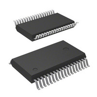
IC 740 MCU FLASH 32K 36-SSOP
Manufacturer
Renesas Electronics America
Series
740/38000r
Datasheet
1.M37542F8FPU0.pdf
(124 pages)
Specifications of M37542F8FP#W4
Core Processor
740
Core Size
8-Bit
Speed
8MHz
Connectivity
SIO, UART/USART
Peripherals
POR, WDT
Number Of I /o
29
Program Memory Size
32KB (32K x 8)
Program Memory Type
FLASH
Ram Size
1K x 8
Voltage - Supply (vcc/vdd)
2.2 V ~ 5.5 V
Data Converters
A/D 8x10b
Oscillator Type
Internal
Operating Temperature
-20°C ~ 85°C
Package / Case
36-SSOP
Lead Free Status / RoHS Status
Lead free / RoHS Compliant
Eeprom Size
-
Available stocks
Company
Part Number
Manufacturer
Quantity
Price


Timer A and Timer B are 16-bit timers and counts the signal which
is the oscillation frequency selected by setting of the timer count
source set register (TCSS). Timer A and Timer B have the same
function except of the count source clock selection.
The count source clock of Timer A is selected from among 1/2,1/
16, 1/32, 1/64, 1/128, 1/256 of f(X
clock.
The count source clock of Timer B is selected from among 1/2, 1/
16, 1/32, 1/64, 1/128, 1/256 of f(X
Timer A (B) consists of the low-order of Timer A: TAL (Timer B:
TBL) and the high-order of Timer A: TAH (Timer B: TBH). Timer A
(B) is decremented by 1 when each time of the count clock is in-
put. When the contents of Timer A (B) reach “0000
underflow occurs at the next count clock, and the timer latch is re-
loaded into timer. When Timer A (B) underflows, the Timer A (B)
interrupt request bit is set to “1”.
Timer A (B) has the Timer A (B) latch to retain the load value. The
value of timer A (B) latch is set to Timer A (B) at the timing of Timer
A (B) underflow. The division ratio of Timer A (B) is 1/(n+1) pro-
vided that the value of Timer A (B) is n.
When writing to both the low-order of Timer A (B) and the high or-
der of Timer A (B) is executed, writing to “latch only” or “latch and
timer” can be selected by the setting value of the timer A (B) write
control bit.
When reading from Timer A (B) register is executed, the count
value of Timer A (B) is read out.
Be sure to write to/read out the low-order of Timer A (B) and the
high-order of Timer A (B) in the following order;
• Read
Read the high-order of Timer A (B) first, and the low-order of Timer
A (B) next and be sure to read both high-order and low-order.
• Write
Write to the low-order of Timer A (B) first, and the high-order of
Timer A (B) next and be sure to write both low-order and high or-
der.
Timer A and Timer B can be used for the timing timer of Input cap-
ture and Output compare function.
7542 Group
Rev.3.03
REJ03B0006-0303
Timer A,B
Jul 11, 2008
Page 34 of 117
IN
IN
) clock and Timer A underflow.
) clock and on-chip oscillator
16
”, an
(1) Setting of timer value
When “1: Write to only latch” is set to the timer A (B) write control
bit, written data to timer register is set to only latch even if timer is
stopped. Accordingly, in order to set the initial value for timer when
it is stopped, set “0: Write to latch and timer simultaneously” to
timer A (B) write control bit.
(2) Read/write of timer A
Stop timer A to read/write its data when the system is in the follow-
ing state;
• CPU operation clock source: X
• Timer A count source: On-chip oscillator output
(3) Read/write of timer B
Stop timer B to read/write its data when the system is in the fol-
lowing state;
• CPU operation clock source: X
• Timer B count source: Timer A underflow
• Timer A count source: On-chip oscillator output
Notes on Timer A, B
IN
IN
oscillation
oscillation
Related parts for M37542F8FP#W4
Image
Part Number
Description
Manufacturer
Datasheet
Request
R

Part Number:
Description:
KIT STARTER FOR M16C/29
Manufacturer:
Renesas Electronics America
Datasheet:

Part Number:
Description:
KIT STARTER FOR R8C/2D
Manufacturer:
Renesas Electronics America
Datasheet:

Part Number:
Description:
R0K33062P STARTER KIT
Manufacturer:
Renesas Electronics America
Datasheet:

Part Number:
Description:
KIT STARTER FOR R8C/23 E8A
Manufacturer:
Renesas Electronics America
Datasheet:

Part Number:
Description:
KIT STARTER FOR R8C/25
Manufacturer:
Renesas Electronics America
Datasheet:

Part Number:
Description:
KIT STARTER H8S2456 SHARPE DSPLY
Manufacturer:
Renesas Electronics America
Datasheet:

Part Number:
Description:
KIT STARTER FOR R8C38C
Manufacturer:
Renesas Electronics America
Datasheet:

Part Number:
Description:
KIT STARTER FOR R8C35C
Manufacturer:
Renesas Electronics America
Datasheet:

Part Number:
Description:
KIT STARTER FOR R8CL3AC+LCD APPS
Manufacturer:
Renesas Electronics America
Datasheet:
Part Number:
Description:
KIT STARTER FOR RX610
Manufacturer:
Renesas Electronics America
Datasheet:

Part Number:
Description:
KIT STARTER FOR R32C/118
Manufacturer:
Renesas Electronics America
Datasheet:

Part Number:
Description:
KIT DEV RSK-R8C/26-29
Manufacturer:
Renesas Electronics America
Datasheet:

Part Number:
Description:
KIT STARTER FOR SH7124
Manufacturer:
Renesas Electronics America
Datasheet:

Part Number:
Description:
KIT STARTER FOR H8SX/1622
Manufacturer:
Renesas Electronics America
Datasheet:

Part Number:
Description:
KIT DEV FOR SH7203
Manufacturer:
Renesas Electronics America
Datasheet: