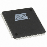
AT91M63200-25AI Atmel, AT91M63200-25AI Datasheet - Page 139

AT91M63200-25AI
Manufacturer Part Number
AT91M63200-25AI
Description
IC ARM7 MCU 176 TQFP
Manufacturer
Atmel
Series
AT91SAMr
Datasheets
1.AT91M43300-25CI.pdf
(21 pages)
2.AT91M43300-25CI.pdf
(5 pages)
3.AT91M63200-25AI.pdf
(12 pages)
4.AT91M63200-25AI.pdf
(153 pages)
Specifications of AT91M63200-25AI
Core Processor
ARM7
Core Size
16/32-Bit
Speed
25MHz
Connectivity
EBI/EMI, SPI, UART/USART
Peripherals
POR, WDT
Number Of I /o
58
Program Memory Type
OTP
Ram Size
2K x 8
Voltage - Supply (vcc/vdd)
1.8 V ~ 3.6 V
Oscillator Type
External
Operating Temperature
-40°C ~ 85°C
Package / Case
176-TQFP, 176-VQFP
Lead Free Status / RoHS Status
Contains lead / RoHS non-compliant
Eeprom Size
-
Program Memory Size
-
Data Converters
-
Available stocks
Company
Part Number
Manufacturer
Quantity
Price
PMC: Power Management Controller
The AT91M63200 Power Management Controller allows
optimization of power consumption. The PMC controls the
system clocks and the peripheral clocks. Two sets of regis-
ters are mapped in the user interface in order to enable and
to disable these clocks.
System Clock
The AT91M63200 has only one system clock: the ARM
core clock. It can be enabled and disabled by writing the
System Clock Enable (PMC_SCER) and System Clock
Disable Registers (PMC_SCDR). The status of this clock
(at least for debug purpose) can be read in the System
Clock Status Register (PMC_SCSR).
The ARM core clock is enabled after a reset and is auto-
matically re-enabled by any enabled interrupt.
When the ARM core clock is disabled, the current instruc-
tion is finished before the clock is stopped.
Note: Stopping the ARM core does not prevent PDC trans-
fers.
PMC User Interface
Base Address:
Table 17. PMC Memory Map
Offset
0x0C
0x00
0x04
0x08
0x10
0x14
0x18
Register
System Clock Enable Register
System Clock Disable Register
System Clock Status Register
Reserved
Peripheral Clock Enable Register
Peripheral Clock Disable Register
Peripheral Clock Status Register
0xFFFF4000
Peripheral Clocks
The clock of each peripheral integrated in the AT91M63200
can be individually enabled and disabled by writing in the
Peripheral Clock Enable (PMC_PCER) and Peripheral
Clock Disable Registers (PMC_PCDR). The status of the
peripheral clocks can be read in the Peripheral Clock Sta-
tus Register (PMC_PCSR).
When a peripheral clock is disabled, the clock is immedi-
ately stopped. When the clock is re-enabled, the peripheral
resumes action where it left off.
In order to stop a peripheral, it is recommended that the
system software waits until the peripheral has executed its
last programmed operation before disabling the clock. This
is to avoid data corruption or erroneous behavior of the
system.
The peripheral clocks are automatically disabled after a
reset.
The bits defined to control the clocks of the peripherals cor-
respond to the bits controlling the interrupt sources in the
AIC.
PMC_SCER
PMC_SCDR
PMC_SCSR
PMC_PCER
PMC_PCDR
PMC_PCSR
Name
AT91M63200
Write only
Write only
Read only
Write only
Write only
Read only
Access
Reset State
0x1
0x0
–
–
–
–
139


