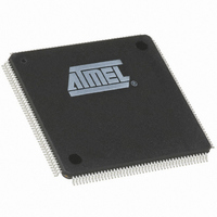
AT91M63200-25AI Atmel, AT91M63200-25AI Datasheet - Page 77

AT91M63200-25AI
Manufacturer Part Number
AT91M63200-25AI
Description
IC ARM7 MCU 176 TQFP
Manufacturer
Atmel
Series
AT91SAMr
Datasheets
1.AT91M43300-25CI.pdf
(21 pages)
2.AT91M43300-25CI.pdf
(5 pages)
3.AT91M63200-25AI.pdf
(12 pages)
4.AT91M63200-25AI.pdf
(153 pages)
Specifications of AT91M63200-25AI
Core Processor
ARM7
Core Size
16/32-Bit
Speed
25MHz
Connectivity
EBI/EMI, SPI, UART/USART
Peripherals
POR, WDT
Number Of I /o
58
Program Memory Type
OTP
Ram Size
2K x 8
Voltage - Supply (vcc/vdd)
1.8 V ~ 3.6 V
Oscillator Type
External
Operating Temperature
-40°C ~ 85°C
Package / Case
176-TQFP, 176-VQFP
Lead Free Status / RoHS Status
Contains lead / RoHS non-compliant
Eeprom Size
-
Program Memory Size
-
Data Converters
-
Available stocks
Company
Part Number
Manufacturer
Quantity
Price
Break
A break condition is a low signal level which has a duration
of at least one character (including start/stop bits and par-
ity).
Transmit Break
The transmitter generates a break condition on the TXD
line when STTBRK is set in US_CR (Control Register). In
this case, the character present in the Transmit Shift Regis-
ter is completed before the line is held low.
To cancel a break condition on the TXD line, the STPBRK
command in US_CR must be set. The USART completes a
minimum break duration of one character length. The TXD
line then returns to high level (idle state) for at least 12 bit
periods to ensure that the end of break is correctly
detected. Then the transmitter resumes normal operation.
The BREAK is managed like a character:
•
•
•
In order to avoid unpredictable states:
•
•
•
•
•
•
The standard break transmission sequence is:
1. Wait for the transmitter ready
2. Send the STTBRK command
The STTBRK and the STPBRK commands are
performed only if the transmitter is ready (bit TXRDY = 1
in US_CSR).
The STTBRK command blocks the transmitter holding
register (bit TXRDY is cleared in US_CSR) until the
break has started.
A break is started when the Shift Register is empty (any
previous character is fully transmitted).
US_CSR.TXEMPTY is cleared. The break blocks the
transmitter shift register until it is completed (high level
for at least 12 bit periods after the STPBRK command is
requested).
STTBRK and STPBRK commands must not be
requested at the same time.
Once an STTBRK command is requested, further
STTBRK commands are ignored until the BREAK is
ended (high level for at least 12 bit periods).
All STPBRK commands requested without a previous
STTBRK command are ignored.
A byte written into the Transmit Holding Register while a
break is pending but not started (bit TXRDY = 0 in
US_CSR) is ignored.
It is not permitted to write new data in the Transmit
Holding Register while a break is in progress (STPBRK
has not been requested), even though TXRDY = 1 in
US_CSR.
A new STTBRK command must not be issued until an
existing break has ended (TXEMPTY = 1 in US_CSR).
(US_CSR.TXRDY = 1).
(write 0x0200 to US_CR).
3. Wait for the transmitter ready
4. Send the STPBRK command
The next byte can then be sent:
5. Wait for the transmitter ready
6. Send the next byte
Each of these steps can be scheduled by using the inter-
rupt if the bit TXRDY in US_IMR is set.
For character transmission, the USART channel must be
enabled before sending a break.
Receive Break
The receiver detects a break condition when all data, parity
and stop bits are low. When the low stop bit is detected, the
receiver asserts the RXBRK bit in US_CSR. An end-of-
receive break is detected by a high level for at least 2/16 of
a bit period in asynchronous operating mode or at least one
sample in synchronous operating mode. RXBRK is also
asserted when an end-of-break is detected.
Both the beginning and the end of a break can be detected
by interrupt if the bit US_IMR.RXBRK is set.
Peripheral Data Controller
Each USART channel is closely connected to a corre-
sponding Peripheral Data Controller channel. One is dedi-
cated to the receiver. The other is dedicated to the trans-
mitter.
Note: The PDC is disabled if 9-bit character length is
selected (MODE9 = 1) in US_MR.
The PDC channel is programmed using US_TPR (Transmit
Pointer) and US_TCR (Transmit Counter) for the transmit-
ter and US_RPR (Receive Pointer) and US_RCR (Receive
Counter) for the receiver. The status of the PDC is given in
US_CSR by the ENDTX bit for the transmitter and by the
ENDRX bit for the receiver.
The pointer registers (US_TPR and US_RPR) are used to
store the address of the transmit or receive buffers. The
counter registers (US_TCR and US_RCR) are used to
store the size of these buffers.
The receiver data transfer is triggered by the RXRDY bit
and the transmitter data transfer is triggered by TXRDY.
When a transfer is performed, the counter is decremented
and the pointer is incremented. When the counter reaches
0, the status bit is set (ENDRX for the receiver, ENDTX for
the transmitter in US_CSR) and can be programmed to
generate an interrupt. Transfers are then disabled until a
new non-zero counter value is programmed.
(bit TXRDY = 1 in US_CSR).
(write 0x0400 to US_CR).
(bit TXRDY = 1 in US_CSR).
(write byte to US_THR).
AT91M63200
77


