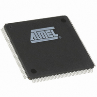
AT91M63200-25AI Atmel, AT91M63200-25AI Datasheet - Page 35

AT91M63200-25AI
Manufacturer Part Number
AT91M63200-25AI
Description
IC ARM7 MCU 176 TQFP
Manufacturer
Atmel
Series
AT91SAMr
Datasheets
1.AT91M43300-25CI.pdf
(21 pages)
2.AT91M43300-25CI.pdf
(5 pages)
3.AT91M63200-25AI.pdf
(12 pages)
4.AT91M63200-25AI.pdf
(153 pages)
Specifications of AT91M63200-25AI
Core Processor
ARM7
Core Size
16/32-Bit
Speed
25MHz
Connectivity
EBI/EMI, SPI, UART/USART
Peripherals
POR, WDT
Number Of I /o
58
Program Memory Type
OTP
Ram Size
2K x 8
Voltage - Supply (vcc/vdd)
1.8 V ~ 3.6 V
Oscillator Type
External
Operating Temperature
-40°C ~ 85°C
Package / Case
176-TQFP, 176-VQFP
Lead Free Status / RoHS Status
Contains lead / RoHS non-compliant
Eeprom Size
-
Program Memory Size
-
Data Converters
-
Available stocks
Company
Part Number
Manufacturer
Quantity
Price
MPI: Multi-processor Interface
The AT91M63200 family features a second bus interface
which is dedicated to parallel data transfers with an exter-
nal processing device. The MPI is based on a 1K byte
Dual-port RAM (DPRAM) and an arbiter. Both the ARM
core and the external processor can read and write to any
location in the DPRAM.
In order to avoid conflicts when the ARM core or external
processor is accessing the DPRAM, an arbiter is present.
The external processor makes a bus request (MPI_BR)
and waits until the bus grant (MPI_BG) is asserted before a
read or write access to the DPRAM is made. The external
bus request is synchronized on the main clock of the
AT91M63200 microcontroller before being processed. The
deactivation of the external bus grant is asynchronous and
results from the deactivation of the external bus request.
See Figure 35.
The arbiter always gives priority to the external processor
over the ARM core. If the ARM core is accessing the
DPRAM when an external bus request is made, the ARM
core access is suspended and finished after the bus
request has been removed. Care must be taken that the
Figure 32. MPI Block Diagram
Note: For detailed timing values, see the corresponding datasheet “M63200 Electrical and Mechanical Characteristics” (Lit-
erature No. 1090).
Note: After a hardware reset, pins MPI_NOE, MPI_NLB and MPI_NUB are not enabled by default (see "PIO: Parallel I/O
Controller" on page 55). The user must configure the PIO Controller to enable the corresponding pins for their MPI function.
ASB
Base Address 0x00400000
DPRAM 1K Byte
Arbiter
ARM core is not halted longer than is critical for the applica-
tion.
The external processor accesses the DPRAM like a stan-
dard 16-bit SRAM once the bus grant is active. The control
signals MPI_NOE, MPI_NLB and MPI_NUB are multi-
plexed, respectively, with the PIO signals PB0, PB1 and
PB2. These signals are not mandatory for proper use of the
MPI.
If one or more of these signals are not used, the PIO func-
tion must be selected on the respective pins. Conse-
quently, the PIO controller will drive an active level on the
MPI control signals. As an example, if all three control sig-
nals are not used, the external processor can only perform
16-bit accesses to the DPRAM and the MPI_NCS and
MPI_RNW signals determine the data bus direction. Spe-
cial care must be taken if the MPI_RNW is changed within
the active period of the MPI_NCS. External bus conflicts
may occur in this case.
The ARM core has single cycle 8-, 16-, and 32-bit access
to the DPRAM.
MPI_BR
MPI_BG
AT91M63200
Controller
PIO
MPI_NCS
MPI_RNW
MPI_A[9:1]
MPI_D[15:0]
MPI_NOE
MPI_NLB
MPI_NUB
35


