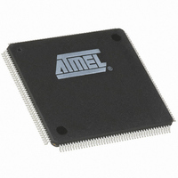
AT91M63200-25AI Atmel, AT91M63200-25AI Datasheet - Page 93

AT91M63200-25AI
Manufacturer Part Number
AT91M63200-25AI
Description
IC ARM7 MCU 176 TQFP
Manufacturer
Atmel
Series
AT91SAMr
Datasheets
1.AT91M43300-25CI.pdf
(21 pages)
2.AT91M43300-25CI.pdf
(5 pages)
3.AT91M63200-25AI.pdf
(12 pages)
4.AT91M63200-25AI.pdf
(153 pages)
Specifications of AT91M63200-25AI
Core Processor
ARM7
Core Size
16/32-Bit
Speed
25MHz
Connectivity
EBI/EMI, SPI, UART/USART
Peripherals
POR, WDT
Number Of I /o
58
Program Memory Type
OTP
Ram Size
2K x 8
Voltage - Supply (vcc/vdd)
1.8 V ~ 3.6 V
Oscillator Type
External
Operating Temperature
-40°C ~ 85°C
Package / Case
176-TQFP, 176-VQFP
Lead Free Status / RoHS Status
Contains lead / RoHS non-compliant
Eeprom Size
-
Program Memory Size
-
Data Converters
-
Available stocks
Company
Part Number
Manufacturer
Quantity
Price
Master Mode
In master mode, the SPI controls data transfers to and from
the slave(s) connected to the SPI bus. The SPI drives the
chip select(s) to the slave(s) and the serial clock (SPCK).
After enabling the SPI, a data transfer begins when the
ARM core writes to the SP_TDR (Transmit Data Register).
See Table 13.
Transmit and receive buffers maintain the data flow at a
constant rate with a reduced requirement for high-priority
interrupt servicing. When new data is available in the
SP_TDR (Transmit Data Register) the SPI continues to
transfer data. If the SP_RDR (Receive Data Register) has
not been read before new data is received, the Overrun
Error (OVRES) flag is set.
The delay between the activation of the chip select and the
start of the data transfer (DLYBS), as well as the delay
between each data transfer (DLYBCT), can be pro-
grammed for each of the four external chip selects. All data
transfer characteristics including the two timing values are
programmed in registers SP_CSR0 to SP_CSR3 (Chip
Select Registers). See Table 13.
In master mode, the peripheral selection can be defined in
two different ways:
•
•
Figures 47 and 48 show the operation of the SPI in master
mode. For details concerning the flag and control bits in
these diagrams, see the tables in the “Programmer’s
Model”, starting on page 99.
Fixed Peripheral Select
This mode is ideal for transferring memory blocks without
the extra overhead in the transmit data register to deter-
mine the peripheral.
Fixed Peripheral Select is activated by setting bit PS to
zero in SP_MR (Mode Register). The peripheral is defined
by the PCS field, also in SP_MR.
This option is only available when the SPI is programmed
in master mode.
Fixed Peripheral Select: SPI exchanges data with only
one peripheral
Variable Peripheral Select: Data can be exchanged with
more than one peripheral
Variable Peripheral Select
Variable Peripheral Select is activated by setting bit PS to
one. The PCS field in SP_TDR (Transmit Data Register) is
used to select the destination peripheral. The data transfer
characteristics are changed when the selected peripheral
changes, according to the associated chip select register.
The PCS field in the SP_MR has no effect.
This option is only available when the SPI is programmed
in master mode.
Chip Selects
The chip select lines are driven by the SPI only if it is pro-
grammed in master mode. These lines are used to select
the destination peripheral. The PCSDEC field in SP_MR
(Mode Register) selects 1 to 4 peripherals (PCSDEC = 0)
or up to 15 peripherals (PCSDEC = 1).
If Variable Peripheral Select is active, the chip select sig-
nals are defined for each transfer in the PCS field in
SP_TDR. Chip select signals can thus be defined indepen-
dently for each transfer.
If Fixed Peripheral Select is active, chip select signals are
defined for all transfers by the field PCS in SP_MR. If a
transfer with a new peripheral is necessary, the software
must wait until the current transfer is completed, then
change the value of PCS in SP_MR before writing new
data in SP_TDR.
The value on the NPCS pins at the end of each transfer
can be read in the SP_RDR (Receive Data Register).
By default, all NPCS signals are high (equal to one) before
and after each transfer.
Mode Fault Detection
A mode fault is detected when the SPI is programmed in
master mode and a low level is driven by an external mas-
ter on the NPCS0/NSS signal.
When a mode fault is detected, the MODF bit in the SP_SR
is set until the SP_SR is read and the SPI is disabled until
re-enabled by bit SPIEN in the SP_CR (Control Register).
AT91M63200
93


