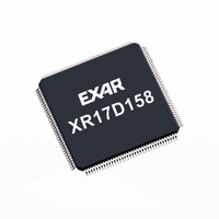
XR17D154IV-F Exar Corporation, XR17D154IV-F Datasheet - Page 31

XR17D154IV-F
Manufacturer Part Number
XR17D154IV-F
Description
IC UART PCI BUS QUAD 144LQFP
Manufacturer
Exar Corporation
Type
IrDA or RS- 485r
Datasheet
1.XR17D154CV-F.pdf
(69 pages)
Specifications of XR17D154IV-F
Number Of Channels
4, QUART
Package / Case
144-LQFP
Features
*
Fifo's
64 Byte
Protocol
RS485
Voltage - Supply
3.3V, 5V
With Auto Flow Control
Yes
With Irda Encoder/decoder
Yes
With False Start Bit Detection
Yes
With Modem Control
Yes
Mounting Type
Surface Mount
Data Rate
6.25 Mbps
Supply Voltage (max)
5.5 V
Supply Voltage (min)
3 V
Supply Current
4 mA
Maximum Operating Temperature
+ 85 C
Minimum Operating Temperature
- 40 C
Mounting Style
SMD/SMT
Operating Supply Voltage
3.3 V or 5 V
No. Of Channels
4
Uart Features
Tx/Rx FIFO Counters
Supply Voltage Range
3V To 5.5V
Operating Temperature Range
-40°C To +85°C
Digital Ic Case Style
LQFP
Rohs Compliant
Yes
Lead Free Status / RoHS Status
Lead free / RoHS Compliant
Lead Free Status / RoHS Status
Lead free / RoHS Compliant, Lead free / RoHS Compliant
Other names
1016-1290
Available stocks
Company
Part Number
Manufacturer
Quantity
Price
Company:
Part Number:
XR17D154IV-F
Manufacturer:
ADI
Quantity:
1 046
Company:
Part Number:
XR17D154IV-F
Manufacturer:
Exar Corporation
Quantity:
10 000
xr
REV. 1.2.2
Automatic hardware RTS/CTS or DTR/DSR flow control is used to prevent data overrun to the local receiver
FIFO and remote receiver FIFO. The RTS#/DTR# output pin is used to request the remote unit to suspend/
restart data transmission while the CTS#/DSR# input pin is monitored to suspend/restart the local transmitter.
The auto RTS/CTS or DTR/DSR flow control features are individually selected to fit specific application
requirement and enabled through EFR bit-6 and 7 and MCR bit-2 for either RTS/CTS or DTR/DSR control
signals.
Auto RTS flow control must be started by asserting the RTS# output pin LOW (MCR bit-1 = 1). Similarly, Auto
DTR flow control must be started by asserting the DTR# output pin LOW (MCR bit-0 = 1).
detail how automatic hardware flow control works.
F
5.4
5.3.3
IGURE
Receive Data
Byte and Errors
16X or 8X Sampling
Clock (8XMODE Reg.)
MCR B
15. R
Automatic Hardware (RTS/CTS or DTR/DSR) Flow Control Operation
64 bytes by 11-
bit wide FIFO
Receiver Operation with FIFO
X
0
0
1
1
IT
ECEIVER
-2
T
ABLE
O
PERATION IN
11: A
Receive Data Shift
EFR B
Register (RSR)
Receive Data
UTO
X
X
1
1
0
Receive
(64-byte)
IT
Data
FIFO
FIFO
-7
RTS/CTS
AND
F
Data falls to 40
FIFO Trigger=48
Data fills to 56
Validation
OR
Data Bit
LOW
Example:
- FIFO trigger level set at 48 bytes
- RTS/DTR hyasteresis set at +/-8 chars.
DTR/DSR F
EFR B
C
31
ONTROL
X
1
X
1
0
UNIVERSAL (3.3V AND 5V) PCI BUS QUAD UART
IT
-6
RTS#/DTR# re-asserts when data falls below the
trigger level to restart remote transmitter.
Enable by EFR bit-6=1, MCR bit-2.
RTS#/DTR# de-asserts when data fills above
the trigger level to suspend remote transmitter.
Enable by EFR bit-6=1, MCR bit-2.
RHR Interrupt (ISR bit-2) is programmed at
FIFO trigger level (RXTRG).
FIFO is Enable by FCR bit-0=1
M
LOW
ODE
C
ONTROL
H
ARDWARE
Auto CTS Flow Control Enabled
Auto DSR Flow Control Enabled
Auto DTR Flow Control Enabled
Auto RTS Flow Control Enabled
No Hardware Flow Control
S
Receive Data Characters
ELECTION
F
LOW
C
ONTROL
Figure 16
S
ELECTION
RXFIFO1
XR17D154
shows in


