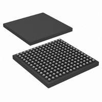
HSP50216KIZ Intersil, HSP50216KIZ Datasheet - Page 14

HSP50216KIZ
Manufacturer Part Number
HSP50216KIZ
Description
IC DOWNCONVERTER DGTL 4CH 196BGA
Manufacturer
Intersil
Datasheet
1.HSP50216KIZ.pdf
(58 pages)
Specifications of HSP50216KIZ
Function
Downconverter
Rf Type
W-CDMA
Package / Case
196-BGA
Lead Free Status / RoHS Status
Lead free / RoHS Compliant
Sample filter #2 requires:
• 32 + 32 + 128 + 8 = 200 data RAM locations
• (95+1)/2=48 coefficient RAM location (resampler and HBF
The number of clock cycles required to compute an output
for Sample filter #2 is calculated as follows:
Total decimation is 8, so the input sample rate for the FIR
chain (CIC output rate) could be up to:
f
With a 65MHz clock, this would support a maximum input
sample rate to the FIR processor of 4.6MHz and an output
sample rate up to 0.580MHz. The shaping filter impulse
response length would be:
(95 x 2)/580,000 = 82μs.
The maximum output sample rate is dependent on the
length and number of FIRs and their decimation factors.
CLK
coefficients are in ROM).
CYCLES
CLOCK
/(ceil(105/8)) = f
SAMPLE FILTER #2 CLOCK CYCLES CALCULATION
105
20
14
48
8
4
2
6
1
1
1
Halfband 1 compute clocks
(5 per compute x 4 computes)
Halfband 1 input sample writes (8 input samples)
Halfband 2 compute clocks
(7 per compute x 2 computes)
Halfband 2 input sample writes (4 input samples)
95 tap symmetric FIR, 2 clocks per tap
FIR input sample writes (2 input samples)
resampler (6 taps, nonsymmetric)
Resampler input sample write (1 input samples)
Jump instruction
Wait instruction
Clock cycles per output
CLK
/14.
FUNCTION PERFORMED
14
HSP50216
Illustrating this concept with Filter Example #3, a higher speed
filter chain might be comprised of one 19 tap decimate-by-2
halfband filter followed by a 30 tap shaping FIR filter with no
decimation. The program for this example could be:
The number of clock cycles required to compute an output
for Sample filter #3 is calculated as follows:
For Filter Example #3 and a 65MSPS input, the maximum
FIR input rate would be 65MSPS/ceil(26/2) = 5MSPS giving
a decimate-by-2 output sample rate of 2.5MSPS. At
70MSPS, the FIR could have up to 34 taps with the same
output rate.
Channels 0, 1, 2 and 3 can be combined in a polyphase
structure for increased bandwidth or improved filtering.
CYCLES
CLOCK
STEP
15
26
SAMPLE FILTER #3 CLOCK CYCLES CALCULATION
0
1
2
3
6
2
1
1
1
FIR
Type = even symmetry
19 taps
Halfband
Decimate by 2
Compute one output
Memory block size 32
Memory block start at 0
Coefficient block start at 18
Output to step 2
Reset wait count
FIR
Type = even symmetry
30 taps
Decimate by 1
Compute one output
Memory block size 64
Memory block start at 32
Coefficient block start at 64
Step size 1
Output to AGC
Jump, Unconditional, to 0
19 tap halfband, one output
halfband input writes (2 input samples)
30 tap symmetric FIR, 2 taps per clock
1 FIR input write
1 wait
1 jump
Clock cycles per output
Wait for enough input samples (2 in this case)
SAMPLE FILTER #3 PROGRAM
FUNCTION PERFORMED
INSTRUCTION
August 17, 2007
FN4557.6


