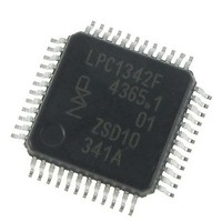
LPC1342FBD48,151 NXP Semiconductors, LPC1342FBD48,151 Datasheet - Page 31

LPC1342FBD48,151
Manufacturer Part Number
LPC1342FBD48,151
Description
IC MCU 32BIT 48LQFP
Manufacturer
NXP Semiconductors
Series
LPC13xxr
Datasheet
1.LPC1342FBD48151.pdf
(62 pages)
Specifications of LPC1342FBD48,151
Core Processor
ARM® Cortex-M3™
Core Size
32-Bit
Speed
72MHz
Connectivity
I²C, Microwire, SPI, SSI, SSP, UART/USART, USB
Peripherals
Brown-out Detect/Reset, POR, WDT
Number Of I /o
40
Program Memory Size
16KB (16K x 8)
Program Memory Type
FLASH
Ram Size
4K x 8
Voltage - Supply (vcc/vdd)
2 V ~ 3.6 V
Data Converters
A/D 8x10b
Oscillator Type
Internal
Operating Temperature
-40°C ~ 85°C
Package / Case
48-LQFP
Processor Series
LPC1342
Core
ARM Cortex-M3
Data Bus Width
32 bit
Data Ram Size
4 KB
Interface Type
I2C, USB, UART
Maximum Clock Frequency
72 MHz
Number Of Programmable I/os
42
Number Of Timers
4
Maximum Operating Temperature
+ 85 C
Mounting Style
SMD/SMT
Minimum Operating Temperature
- 40 C
Lead Free Status / RoHS Status
Lead free / RoHS Compliant
Eeprom Size
-
Lead Free Status / Rohs Status
Details
Other names
568-5214
Available stocks
Company
Part Number
Manufacturer
Quantity
Price
Company:
Part Number:
LPC1342FBD48,151
Manufacturer:
TI
Quantity:
115
Company:
Part Number:
LPC1342FBD48,151
Manufacturer:
NXP Semiconductors
Quantity:
10 000
NXP Semiconductors
Table 7.
T
[1]
[2]
[3]
[4]
[5]
[6]
[7]
[8]
[9]
[10] Including voltage on outputs in 3-state mode.
[11] V
[12] 3-state outputs go into 3-state mode in Deep power-down mode.
[13] Allowed as long as the current limit does not exceed the maximum current allowed by the device.
[14] To V
[15] Includes external resistors of 33 Ω ± 1 % on USB_DP and USB_DM.
Table 8.
T
LPC1311_13_42_43
Product data sheet
Symbol
V
C
E
E
E
E
Symbol Parameter
V
V
V
V
V
V
C
Z
amb
amb
DRV
BUS
DI
CM
th(rs)se
OL
OH
IA
D
L(adj)
O
G
trans
ia
Typical ratings are not guaranteed. The values listed are at room temperature (25 °C), nominal supply voltages.
IRC enabled; system oscillator disabled; system PLL disabled.
I
BOD disabled.
All peripherals disabled in the SYSAHBCLKCTRL register. Peripheral clocks to UART, SSP, trace clock, and SysTick timer disabled in
the syscon block.
For LPC134x: USB_DP and USB_DM pulled LOW externally.
IRC disabled; system oscillator enabled; system PLL enabled.
All oscillators and analog blocks turned off in the PDSLEEPCFG register; PDSLEEPCFG = 0x0000 0FFF.
WAKEUP pin pulled HIGH externally.
DD
= −40 °C to +85 °C, unless otherwise specified.
= −40 °C to +85 °C unless otherwise specified; ADC frequency 4.5 MHz, V
DD
measurements were performed with all pins configured as GPIO outputs driven LOW and pull-up resistors disabled.
SS
supply voltage must be present.
.
bus supply voltage
differential input
sensitivity voltage
differential common
mode voltage range
single-ended receiver
switching threshold
voltage
LOW-level output
voltage
HIGH-level output
voltage
transceiver capacitance pin to GND
driver output
impedance for driver
which is not high-speed
capable
Static characteristics
ADC static characteristics
Parameter
analog input voltage
analog input capacitance
differential linearity error
integral non-linearity
offset error
gain error
…continued
Conditions
|(D+) − (D−)|
includes V
for low-/full-speed;
R
driven; for low-/full-speed;
R
with 33 Ω series resistor; steady state
drive
L
L
of 1.5 kΩ to 3.6 V
of 15 kΩ to GND
All information provided in this document is subject to legal disclaimers.
Conditions
DI
range
Rev. 3 — 10 August 2010
[1][2]
[3]
[4]
[5]
Min
0
-
-
-
-
-
[15]
32-bit ARM Cortex-M3 microcontroller
DD
LPC1311/13/42/43
= 2.5 V to 3.6 V.
Min
-
0.2
0.8
0.8
-
2.8
-
36
Typ
-
-
-
-
-
-
Typ
-
-
-
-
-
-
-
-
[1]
Max
V
1
±1
±1.5
±3.5
0.6
© NXP B.V. 2010. All rights reserved.
DD
Max
5.25
-
2.5
2.0
0.18
3.5
20
44.1
Unit
V
pF
LSB
LSB
LSB
%
31 of 62
Unit
V
V
V
V
V
V
pF
Ω


