QB-MINI2-EE NEC, QB-MINI2-EE Datasheet - Page 151
QB-MINI2-EE
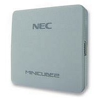
Manufacturer Part Number
QB-MINI2-EE
Description
EMULATOR, PROGRAMMER, MINICUBE2
Manufacturer
NEC
Type
Debug Emulatorr
Datasheet
1.QB-MINI2-EE.pdf
(169 pages)
Specifications of QB-MINI2-EE
Svhc
No SVHC (18-Jun-2010)
Mcu Supported Families
MINICUBE2
Silicon Family Name
V850, 78K0R, 78K0S
Ic Product Type
On-Chip Debug Emulator
Kit Contents
MINICUBE2, USB Cable, Target Cable, 78K0-OCD Board
Features
On-Chip Debugging, Flash Memory Programming,


(d) Securement of stack area for debugging
0xFFEDF
0xFFEDF
0xFCF00
0xFCF00
This area requires 6 bytes as the stack area for debugging. Since this area is allocated immediately before
the stack area, the address of this area varies depending on the stack increase and decrease. That is, 6
extra bytes are consumed for the stack area used.
Figure 6-15 illustrates the case where the stack area is increased when the internal high-speed RAM starts
from 0xFCF00.
[How to secure areas]
Set the stack pointer by estimating the stack area consumed by the user program + 6 bytes. Make sure that
the stack pointer does not extend beyond the internal high-speed RAM start address.
Remark
Refer to the self programming manual for how to secure the stack area for self programming.
6 bytes
6 bytes
<1>
<1>
CHAPTER 6
Figure 6-15. Variation of Address of Stack Area for Debugging
Stack area for
Stack area for
debugging
debugging
Stack area
Stack area
Available space
Available space
In internal high-
In internal high-
speed RAM
speed RAM
HOW TO USE MINICUBE2 WITH 78K0R MICROCONTROLLER
User’s Manual U18371EJ1V0UM
0xFFEDF
0xFFEDF
0xFCF00
0xFCF00
6 bytes
6 bytes
<2>
<2>
0xFFEDF
0xFFEDF
0xFCF06
0xFCF06
0xFCF00
0xFCF00
6 bytes
6 bytes
<3>
<3>
151
Related parts for QB-MINI2-EE
Image
Part Number
Description
Manufacturer
Datasheet
Request
R

Part Number:
Description:
16/8 bit single-chip microcomputer
Manufacturer:
NEC
Datasheet:
Part Number:
Description:
Dual audio power amp circuit
Manufacturer:
NEC
Datasheet:
Part Number:
Description:
Dual comparator
Manufacturer:
NEC
Datasheet:
Part Number:
Description:
MOS type composite field effect transistor
Manufacturer:
NEC
Datasheet:
Part Number:
Description:
50 V/100 mA FET array incorporating 2 N-ch MOSFETs
Manufacturer:
NEC
Datasheet:
Part Number:
Description:
6-pin small MM high-frequency double transistor
Manufacturer:
NEC
Datasheet:
Part Number:
Description:
6-pin small MM high-frequency double transistor
Manufacturer:
NEC
Datasheet:
Part Number:
Description:
6-pin small MM high-frequency double transistor
Manufacturer:
NEC
Datasheet:
Part Number:
Description:
6-pin small MM high-frequency double transistor
Manufacturer:
NEC
Datasheet:
Part Number:
Description:
Twin transistors equipped with different model chips(6P small MM)
Manufacturer:
NEC
Datasheet:
Part Number:
Description:
Bipolar analog integrated circuit
Manufacturer:
NEC
Datasheet: