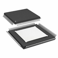
AD9271BSVZRL-25 Analog Devices Inc, AD9271BSVZRL-25 Datasheet - Page 2

AD9271BSVZRL-25
Manufacturer Part Number
AD9271BSVZRL-25
Description
IC ADC OCT 12BIT 25MSPS 100-TQFP
Manufacturer
Analog Devices Inc
Datasheet
1.AD9271BSVZ-50.pdf
(60 pages)
Specifications of AD9271BSVZRL-25
Number Of Bits
12
Sampling Rate (per Second)
25M
Data Interface
Serial, SPI™
Number Of Converters
8
Power Dissipation (max)
1.06W
Voltage Supply Source
Single Supply
Operating Temperature
-40°C ~ 85°C
Mounting Type
Surface Mount
Package / Case
100-TQFP Exposed Pad
Power Dissipation Pd
150mW
Peak Reflow Compatible (260 C)
Yes
Supply Voltage
1.8V
Sample Rate
25 MSPS
Termination Type
SMD
Supply Voltage Max
1.9V
Input Channels Per Adc
8
Lead Free Status / RoHS Status
Lead free / RoHS Compliant
For Use With
AD9271-50EBZ - BOARD EVALUATION AD9271 50MSPS
Lead Free Status / RoHS Status
Lead free / RoHS Compliant, Lead free / RoHS Compliant
Available stocks
Company
Part Number
Manufacturer
Quantity
Price
Company:
Part Number:
AD9271BSVZRL-25
Manufacturer:
AD
Quantity:
1 140
Company:
Part Number:
AD9271BSVZRL-25
Manufacturer:
Analog Devices Inc
Quantity:
10 000
AD9271
TABLE OF CONTENTS
Features .............................................................................................. 1
Applications ....................................................................................... 1
General Description ......................................................................... 1
Functional Block Diagram .............................................................. 1
Revision History ............................................................................... 2
Product Highlights ........................................................................... 3
Specifications ..................................................................................... 4
Absolute Maximum Ratings .......................................................... 10
Pin Configuration and Function Descriptions ........................... 11
Equivalent Circuits ......................................................................... 14
Typical Performance Characteristics ........................................... 16
Theory of Operation ...................................................................... 20
REVISION HISTORY
5/09—Rev. A to Rev. B
Changes to Figure 27 ...................................................................... 17
Changes to Figure 40 and Figure 41 ............................................. 21
Changes to Ordering Guide .......................................................... 58
12/07—Rev. 0 to Rev. A
Change to AC Specifications Text .................................................. 4
Added Input Noise Current ............................................................ 4
Added Noise Figure .......................................................................... 4
Changes to Signal-to-Noise Ratio Units ........................................ 4
Changes to Harmonic Distortion Units ........................................ 5
Added Endnote 3 .............................................................................. 6
Changes to Table 6 .......................................................................... 11
Inserted Figure 19 and Figure 21 .................................................. 16
Changes to Figure 20 ...................................................................... 16
Changes to Theory of Operation Section .................................... 20
Changes to Figure 40 and Figure 41 ............................................. 21
Change to Active Impedance Matching Section ........................ 22
AC Specifications .......................................................................... 4
Digital Specifications ................................................................... 7
Switching Specifications .............................................................. 8
ADC Timing Diagrams ............................................................... 9
Thermal Impedance ................................................................... 10
ESD Caution ................................................................................ 10
Ultrasound ................................................................................... 20
Channel Overview ...................................................................... 21
Input Overdrive .......................................................................... 23
CW Doppler Operation ............................................................. 24
Rev. B | Page 2 of 60
Serial Port Interface (SPI) .............................................................. 35
Memory Map .................................................................................. 37
Applications Information .............................................................. 41
Evaluation Board ............................................................................ 42
Outline Dimensions ....................................................................... 58
Changes to LNA Noise Section .................................................... 22
Changes to Figure 43 ...................................................................... 22
Change to Input Overload Protection Section ........................... 23
Changes to TGC Operation Section ............................................ 25
Changes to Gain Control Section ................................................. 26
Changes to Figure 52 ...................................................................... 26
Change to Table 11 ......................................................................... 33
Changes to Serial Interface Port (SPI) Section ........................... 35
Changes to Hardware Interface Section ...................................... 35
Changes to Reading the Memory Map Table Section ............... 37
Added Applications Information and
Change to Input Signals Section ................................................... 42
Changes to Figure 73 ...................................................................... 42
Changes to Table 16 ....................................................................... 55
6/07—Revision 0: Initial Version
TGC Operation ........................................................................... 25
ADC ............................................................................................. 27
Clock Input Considerations ...................................................... 28
Hardware Interface ..................................................................... 35
Reading the Memory Map Table .............................................. 37
Reserved Locations .................................................................... 37
Default Values ............................................................................. 37
Logic Levels ................................................................................. 37
Design Guidelines ...................................................................... 41
Power Supplies ............................................................................ 42
Input Signals................................................................................ 42
Output Signals ............................................................................ 42
Default Operation and Jumper Selection Settings ................. 43
Quick Start Procedure ............................................................... 44
Schematics and Artwork ........................................................... 45
Ordering Guide .......................................................................... 58
Design Guidelines Sections ...................................................... 41


