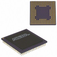
EPM7256EGI192-20 Altera, EPM7256EGI192-20 Datasheet - Page 21

EPM7256EGI192-20
Manufacturer Part Number
EPM7256EGI192-20
Description
IC MAX 7000 CPLD 256 192-PGA
Manufacturer
Altera
Series
MAX® 7000r
Datasheet
1.EPM7064STC44-10.pdf
(66 pages)
Specifications of EPM7256EGI192-20
Programmable Type
In System Programmable
Delay Time Tpd(1) Max
20.0ns
Voltage Supply - Internal
4.5 V ~ 5.5 V
Number Of Logic Elements/blocks
16
Number Of Macrocells
256
Number Of Gates
5000
Number Of I /o
164
Operating Temperature
-40°C ~ 85°C
Mounting Type
Surface Mount
Package / Case
192-PGA
Voltage
5V
Memory Type
EEPROM
Number Of Logic Elements/cells
16
Family Name
MAX 7000
# Macrocells
256
Number Of Usable Gates
5000
Frequency (max)
83.33MHz
Propagation Delay Time
20ns
Number Of Logic Blocks/elements
16
# I/os (max)
164
Operating Supply Voltage (typ)
5V
In System Programmable
Yes
Operating Supply Voltage (min)
4.5V
Operating Supply Voltage (max)
5.5V
Operating Temp Range
-40C to 85C
Operating Temperature Classification
Industrial
Mounting
Through Hole
Pin Count
192
Package Type
CPGA
Lead Free Status / RoHS Status
Contains lead / RoHS non-compliant
Features
-
Lead Free Status / Rohs Status
Compliant
Other names
544-2356
Available stocks
Company
Part Number
Manufacturer
Quantity
Price
Part Number:
EPM7256EGI192-20
Manufacturer:
ALTERA/阿尔特拉
Quantity:
20 000
Programming with
External Hardware
Altera Corporation
f
f
By using an external 5.0-V pull-up resistor, output pins on MAX
7000S devices can be set to meet 5.0-V CMOS input voltages. When
V
pull-up transistor, allowing the external pull-up resistor to pull the
output high enough to meet 5.0-V CMOS input voltages. When
V
because the pull-up transistor will already turn off when the pin
exceeds approximately 3.8 V, allowing the external pull-up resistor to
pull the output high enough to meet 5.0-V CMOS input voltages.
Slew-Rate Control
The output buffer for each MAX 7000E and MAX 7000S I/O pin has
an adjustable output slew rate that can be configured for low-noise
or high-speed performance. A faster slew rate provides high-speed
transitions for high-performance systems. However, these fast
transitions may introduce noise transients into the system. A slow
slew rate reduces system noise, but adds a nominal delay of 4 to 5 ns.
In MAX 7000E devices, when the Turbo Bit is turned off, the slew
rate is set for low noise performance. For MAX 7000S devices, each
I/O pin has an individual EEPROM bit that controls the slew rate,
allowing designers to specify the slew rate on a pin-by-pin basis.
MAX 7000 devices can be programmed on Windows-based PCs with
the Altera Logic Programmer card, the Master Programming Unit
(MPU), and the appropriate device adapter. The MPU performs a
continuity check to ensure adequate electrical contact between the
adapter and the device.
For more information, see the
Sheet.
The Altera development system can use text- or waveform-format
test vectors created with the Text Editor or Waveform Editor to test
the programmed device. For added design verification, designers
can perform functional testing to compare the functional behavior of
a MAX 7000 device with the results of simulation. Moreover, Data
I/O, BP Microsystems, and other programming hardware
manufacturers also provide programming support for Altera
devices.
For more information, see the
CCIO
CCIO
is 3.3 V, setting the open drain option will turn off the output
is 5.0 V, setting the output drain option is not necessary
MAX 7000 Programmable Logic Device Family Data Sheet
Altera Programming Hardware Data
Programming Hardware
Manufacturers.
21


