MCP3909RD-3PH1 Microchip Technology, MCP3909RD-3PH1 Datasheet - Page 43
MCP3909RD-3PH1
Manufacturer Part Number
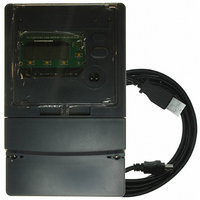
MCP3909RD-3PH1
Description
REF DESIGN MCP3909 3PH ENGY MTR
Manufacturer
Microchip Technology
Datasheets
1.MCP3909T-ISS.pdf
(44 pages)
2.MCP3909T-ISS.pdf
(104 pages)
3.MCP3909RD-3PH3.pdf
(88 pages)
Specifications of MCP3909RD-3PH1
Main Purpose
Power Management, Energy/Power Meter
Embedded
No
Utilized Ic / Part
MCP3909, PIC18F2520, PIC18F4550
Primary Attributes
3-Ph, 220 VAC, In Case, LCD, USB, GUI
Secondary Attributes
Opto-Isolated Interface for Safety
Operating Voltage
220 V
Operating Current
5 A
Description/function
Energy Meter
For Use With/related Products
MCP3909
Lead Free Status / RoHS Status
Not applicable / Not applicable


5.1
© 2008 Microchip Technology Inc.
CALIBRATION OVERVIEW
The method to calculate the values for the calibration registers in Chapter 3 are
described in this chapter. These registers are used to remove offset, set gain and
phase adjustments, and include (units)/LSB adjustments for all the meter outputs. The
calibration flow charts and equations presented in this section are all automated using
Microchip’s “3-phase Energy Meter Calibration Software”, downloadable from Micro-
chip’s energy metering web site. The following calibration routines are described in this
chapter.
• Active Power Calibration
• RMS Current and Voltage Calibration
• Apparent Power Calibration
The method of calibrating these three separate signal flows can be combined into 4 dif-
ferent calibration configurations. These configurations consist of supplying specific
voltages and currents at specific phase angles to the meter during calibration.
In addition, one of the 3 phases needs to be set as the “standard” phase for phase
matching. This process is described in the following sections through steps and flow
charts and is handled automatically by the calibration software described in
Chapter 6. “3-Phase Energy Meter Calibration Software”.
5.1.1
Calibration of the 3-phase power meter involves four different test configurations and
three iterations of each of these four configurations, one iteration for each phase. The
first iteration is typically done on the "standard" phase. This phase represents the
standard that the other two phases must be calibrated to.
For example, meter design example 5(10)A, I
Calibrating the three phase power meter involves these four test configurations:
1. Configuration C1 - Basic voltage V
2. Configuration C2 - Basic voltage V
3. Configuration C3 - Basic voltage V
4. Configuration C4 - 1/10 of Basic voltage V
These calibration configurations are typically steps in a sequence. Almost always,
configuration C1 is the most important and must be done first. The other configurations
require values obtained from configuration C1, but are not dependent on values
obtained from the other configurations. In other words, C1 is probably the first step,
while the other configurations can be done in any order.
For example, 220V and 5A
0.5.
For example, 220V and 50 mA.
For example, 22V and 1A.
Chapter 5. Meter Calibration
I
Configurations
B
, V
B
, PH<s>, PH<un> Meter Constant and Calibration
METER REFERENCE DESIGN
MCP3909 3-PHASE ENERGY
B
B
B
and basic current I
and basic current I
and 1/100 of I
B
= 5, I
B
and 1/10 of I
MAX
B
= 10A.
at a power factor of 1.
B
B
at a power factor of 1.
B
at a power factor of
at a power factor of 1.
DS51643B-page 39
Related parts for MCP3909RD-3PH1
Image
Part Number
Description
Manufacturer
Datasheet
Request
R

Part Number:
Description:
BOARD DES MCP3909 ENERGY METER
Manufacturer:
Microchip Technology
Datasheet:

Part Number:
Description:
REF DESIGN FOR MCP3909 W/18F2520
Manufacturer:
Microchip Technology
Datasheet:

Part Number:
Description:
Manufacturer:
Microchip Technology Inc.
Datasheet:
Part Number:
Description:
Manufacturer:
Microchip Technology Inc.
Datasheet:
Part Number:
Description:
Manufacturer:
Microchip Technology Inc.
Datasheet:
Part Number:
Description:
Manufacturer:
Microchip Technology Inc.
Datasheet:
Part Number:
Description:
Manufacturer:
Microchip Technology Inc.
Datasheet:
Part Number:
Description:
Manufacturer:
Microchip Technology Inc.
Datasheet:
Part Number:
Description:
Manufacturer:
Microchip Technology Inc.
Datasheet:
Part Number:
Description:
Manufacturer:
Microchip Technology Inc.
Datasheet: