MCP3909RD-3PH1 Microchip Technology, MCP3909RD-3PH1 Datasheet - Page 60
MCP3909RD-3PH1
Manufacturer Part Number
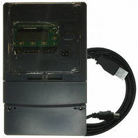
MCP3909RD-3PH1
Description
REF DESIGN MCP3909 3PH ENGY MTR
Manufacturer
Microchip Technology
Datasheets
1.MCP3909T-ISS.pdf
(44 pages)
2.MCP3909T-ISS.pdf
(104 pages)
3.MCP3909RD-3PH3.pdf
(88 pages)
Specifications of MCP3909RD-3PH1
Main Purpose
Power Management, Energy/Power Meter
Embedded
No
Utilized Ic / Part
MCP3909, PIC18F2520, PIC18F4550
Primary Attributes
3-Ph, 220 VAC, In Case, LCD, USB, GUI
Secondary Attributes
Opto-Isolated Interface for Safety
Operating Voltage
220 V
Operating Current
5 A
Description/function
Energy Meter
For Use With/related Products
MCP3909
Lead Free Status / RoHS Status
Not applicable / Not applicable


MCP3909 3-Phase Energy Meter Reference Design
6.3
DS51643B-page 56
SOFTWARE OVERVIEW AND TAB CONTROL
The software has three tabs at the top that correspond to three different frames in the
main screen.
The results frame shows the power readings coming back from the meter, such as
active power, apparent power, RMS current and RMS voltage.
The log frame shows the message logs that are used to record all activity that is taking
place inside the software during calibration, reading, writing registers, etc.
The communications frame shows all USB activity that takes place during calibration
or meter reading. This can be used to track activity and generate customized meter
calibration scripts.
Note that at software start, the program polls to see if the meter is connected to the PC
via USB. If the meter hardware is found connected (or not connected), an appropriate
message is placed in the scrolling message/status window, e.g. “Meter not connected
(PID0x0xx)”, and the icon in the bottom right hand corner of the results window is
turned red. When a meter is connected, the icon is green and the software refreshes
all visible registers and calibration icons.
• Results
• Log
• Communications
© 2008 Microchip Technology Inc.
Related parts for MCP3909RD-3PH1
Image
Part Number
Description
Manufacturer
Datasheet
Request
R

Part Number:
Description:
BOARD DES MCP3909 ENERGY METER
Manufacturer:
Microchip Technology
Datasheet:

Part Number:
Description:
REF DESIGN FOR MCP3909 W/18F2520
Manufacturer:
Microchip Technology
Datasheet:

Part Number:
Description:
Manufacturer:
Microchip Technology Inc.
Datasheet:
Part Number:
Description:
Manufacturer:
Microchip Technology Inc.
Datasheet:
Part Number:
Description:
Manufacturer:
Microchip Technology Inc.
Datasheet:
Part Number:
Description:
Manufacturer:
Microchip Technology Inc.
Datasheet:
Part Number:
Description:
Manufacturer:
Microchip Technology Inc.
Datasheet:
Part Number:
Description:
Manufacturer:
Microchip Technology Inc.
Datasheet:
Part Number:
Description:
Manufacturer:
Microchip Technology Inc.
Datasheet:
Part Number:
Description:
Manufacturer:
Microchip Technology Inc.
Datasheet: