MCP3909RD-3PH1 Microchip Technology, MCP3909RD-3PH1 Datasheet - Page 63
MCP3909RD-3PH1
Manufacturer Part Number
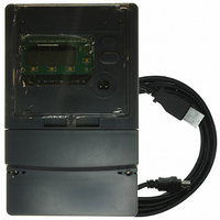
MCP3909RD-3PH1
Description
REF DESIGN MCP3909 3PH ENGY MTR
Manufacturer
Microchip Technology
Datasheets
1.MCP3909T-ISS.pdf
(44 pages)
2.MCP3909T-ISS.pdf
(104 pages)
3.MCP3909RD-3PH3.pdf
(88 pages)
Specifications of MCP3909RD-3PH1
Main Purpose
Power Management, Energy/Power Meter
Embedded
No
Utilized Ic / Part
MCP3909, PIC18F2520, PIC18F4550
Primary Attributes
3-Ph, 220 VAC, In Case, LCD, USB, GUI
Secondary Attributes
Opto-Isolated Interface for Safety
Operating Voltage
220 V
Operating Current
5 A
Description/function
Energy Meter
For Use With/related Products
MCP3909
Lead Free Status / RoHS Status
Not applicable / Not applicable


6.5
6.6
6.7
© 2008 Microchip Technology Inc.
CALIBRATION ICONS
REGISTER LIST
WRITING TO INDIVIDUAL REGISTERS
The results frame contains small symbols that represent if a given calibration STEP has
occurred, and a given calibration register has been written, or not.
There are 5 symbols for total that represent the steps of calibration.
The status of these symbols (enabled / disabled) are saved in the PH_Y_CAL_STATUS
registers and is loaded when the software detects a meter connected to the PC. A
yellow icon represents that a given step HAS OCCURED.
It should be noted that the CF icon can only be enabled in 1 of the 3 phases. This is
because only 1 phase can be selected as the ‘standard phase’, and the other phases
must then be gained matched to this standard phase. For this reason you will note that
the gain icons for active power and apparent power ‘G’ are disabled in the standard
phase by turning a dark grey color.
For more information on the various steps of calibration, refer to Chapter 5. “Meter
Calibration”.
The results screen also includes a complete list of the registers, their address, name,
width, state (readable (R) or readable and writable (R/W)), value, description, and if
they have been selected for monitor refresh.
Unless they have been selected to be monitored, the registers in this frame are NOT
updated every 2.5 seconds like the meter reading section. To refresh the complete
register list, select “Refresh” from the menu.
To select a specific register for monitor, right click on the row in this frame and then
select “monitor” from the menu by left-clicking.
While not recommended as it will interfere with the calibration process, it is possible to
write to individual registers. All writes to registers is automated during the calibration
process, and it should not be necessary to write to a specific register to calibrate a
meter. However you can perform writes to your meter and test various configurations
by writing to the registers individually.
To write a value to a specific register, right click on the register and then select “write
value” on the menu by left clicking. At this point, you will be asked the value to be
written to the meter.
• CF for standard phase calibration
• φ - Phase delay
• O - Offset
• G - Gain
• L - GLSB
3-Phase Energy Meter Calibration Software
DS51643B-page 59
Related parts for MCP3909RD-3PH1
Image
Part Number
Description
Manufacturer
Datasheet
Request
R

Part Number:
Description:
BOARD DES MCP3909 ENERGY METER
Manufacturer:
Microchip Technology
Datasheet:

Part Number:
Description:
REF DESIGN FOR MCP3909 W/18F2520
Manufacturer:
Microchip Technology
Datasheet:

Part Number:
Description:
Manufacturer:
Microchip Technology Inc.
Datasheet:
Part Number:
Description:
Manufacturer:
Microchip Technology Inc.
Datasheet:
Part Number:
Description:
Manufacturer:
Microchip Technology Inc.
Datasheet:
Part Number:
Description:
Manufacturer:
Microchip Technology Inc.
Datasheet:
Part Number:
Description:
Manufacturer:
Microchip Technology Inc.
Datasheet:
Part Number:
Description:
Manufacturer:
Microchip Technology Inc.
Datasheet:
Part Number:
Description:
Manufacturer:
Microchip Technology Inc.
Datasheet:
Part Number:
Description:
Manufacturer:
Microchip Technology Inc.
Datasheet: