MCP3909RD-3PH1 Microchip Technology, MCP3909RD-3PH1 Datasheet - Page 44
MCP3909RD-3PH1
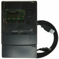
Manufacturer Part Number
MCP3909RD-3PH1
Description
REF DESIGN MCP3909 3PH ENGY MTR
Manufacturer
Microchip Technology
Datasheets
1.MCP3909T-ISS.pdf
(44 pages)
2.MCP3909T-ISS.pdf
(104 pages)
3.MCP3909RD-3PH3.pdf
(88 pages)
Specifications of MCP3909RD-3PH1
Main Purpose
Power Management, Energy/Power Meter
Embedded
No
Utilized Ic / Part
MCP3909, PIC18F2520, PIC18F4550
Primary Attributes
3-Ph, 220 VAC, In Case, LCD, USB, GUI
Secondary Attributes
Opto-Isolated Interface for Safety
Operating Voltage
220 V
Operating Current
5 A
Description/function
Energy Meter
For Use With/related Products
MCP3909
Lead Free Status / RoHS Status
Not applicable / Not applicable


MCP3909 3-Phase Energy Meter Reference Design
DS51643B-page 40
Typically, phase A is the standard phase that the other two phases (B and C) are
calibrated to. However, there is no particular reason why this should be the case. Still,
there needs to be a way of signifying the standard phase. This document uses the
shorthand PHy<register name> to stand for an arbitrary register. For example,
PHy_W_GAIN stands for PHA_W_GAIN, PHB_W_GAIN, and PHC_W_GAIN.
The notation PH<s>… stands for the standard phase register whose value was
obtained from the three phase power meter during calibration setup C1. The notation
PH<u1> represents one of the two uncalibrated phases while PH<u2> represents the
other. In general, the calibration routines focus on the PH<u1> registers while the
PH<u2> registers would be calculated in the same way.
The meter constant is typically given in units of impulses per kilo-watt hour. As an
example, the calibration output frequency of CF, METER_CONSTANT =
3200 imp/kWh or 6400 imp/kWh.
Note:
To calibrate the offset for RMS voltage for a given phase at 1/10 of Vcal, the
meter must have power from one of the other two phases.
© 2008 Microchip Technology Inc.
Related parts for MCP3909RD-3PH1
Image
Part Number
Description
Manufacturer
Datasheet
Request
R

Part Number:
Description:
BOARD DES MCP3909 ENERGY METER
Manufacturer:
Microchip Technology
Datasheet:

Part Number:
Description:
REF DESIGN FOR MCP3909 W/18F2520
Manufacturer:
Microchip Technology
Datasheet:

Part Number:
Description:
Manufacturer:
Microchip Technology Inc.
Datasheet:
Part Number:
Description:
Manufacturer:
Microchip Technology Inc.
Datasheet:
Part Number:
Description:
Manufacturer:
Microchip Technology Inc.
Datasheet:
Part Number:
Description:
Manufacturer:
Microchip Technology Inc.
Datasheet:
Part Number:
Description:
Manufacturer:
Microchip Technology Inc.
Datasheet:
Part Number:
Description:
Manufacturer:
Microchip Technology Inc.
Datasheet:
Part Number:
Description:
Manufacturer:
Microchip Technology Inc.
Datasheet:
Part Number:
Description:
Manufacturer:
Microchip Technology Inc.
Datasheet: