MCP3909RD-3PH1 Microchip Technology, MCP3909RD-3PH1 Datasheet - Page 45
MCP3909RD-3PH1
Manufacturer Part Number
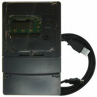
MCP3909RD-3PH1
Description
REF DESIGN MCP3909 3PH ENGY MTR
Manufacturer
Microchip Technology
Datasheets
1.MCP3909T-ISS.pdf
(44 pages)
2.MCP3909T-ISS.pdf
(104 pages)
3.MCP3909RD-3PH3.pdf
(88 pages)
Specifications of MCP3909RD-3PH1
Main Purpose
Power Management, Energy/Power Meter
Embedded
No
Utilized Ic / Part
MCP3909, PIC18F2520, PIC18F4550
Primary Attributes
3-Ph, 220 VAC, In Case, LCD, USB, GUI
Secondary Attributes
Opto-Isolated Interface for Safety
Operating Voltage
220 V
Operating Current
5 A
Description/function
Energy Meter
For Use With/related Products
MCP3909
Lead Free Status / RoHS Status
Not applicable / Not applicable


5.2
FIGURE 5-1:
© 2008 Microchip Technology Inc.
VOLTAGE
CURRENT
ADC
ADC
MCP3909
ACTIVE POWER SIGNAL FLOW AND CALIBRATION
ENERGY_W_L_RAW:48
ENERGY_W_L:32
ENERGY_W_Z:64
5.2.1
The active power signal flow has two separate signal paths. The first path is a total of
all 3 phases and leads to both the CF output pulse frequency, which is proportional to
the total active power being measured by the energy meter, and the active energy
registers, again, which are functions of all three phases. These energy outputs are in
units of kWh and can also be phase gated using the MODE1 register. The second path
is unique to each phase and leads to the active power output registers (PHy_W). Each
phase has its own separate active power registers.
Table 5-1 represents the registers being set during active power calibration.
TABLE 5-1:
Active Power Signal Path showing Output and Calibration Registers.
Phy_W:32
PHy_DELAY:8
ENERGY_W_GLSB
ENERGY_W:64
Note:
Register Name
PHy_W_GLSB
PHy_W_GAIN
PHy_W_OFF
PHy_DELAY
CFNUM
CFDEN
ENERGY_W_GLSB:16 (NOT IMPLEMENTED)
Φ
Active Power Calibration Overview & Signal Path
Important! There are two important items to consider when calibrating a meter. The first is that
each phase must be calibrated separately for the meter to be entirely calibrated. The second
item is that since the second signal path includes all 3 phases (CF output and ENERGY), one
of the phases must be used to coarsely adjust the calibration registers in this path (CFNUM,
CFDEN, and ENERGY_W_GLSB). This phase is the “standard phase”. The other two phases
can then be ‘fine tuned’ to gain match the standard phase by adjusting the registers in these
paths prior to the three phase summation (PHy_W_GAIN, and PHy_VA_GAIN). These regis-
ters MUST be set after the coarse registers have been set by one of the three phases.
kWh
kW
CALIBRATION REGISTERS GENERATED THROUGH THIS ROUTINE
PHy_W_GLSB:16
X
X
PHy_W_OFF:32
X
Not Implemented
Note 1:
PERIOD:16 (INTERNAL REGISTER)
Section 5.3.3
Section 5.3.3
Section 5.3.5
Section 5.3.7
Section 5.3.9
Section 5.3.3
Equations
Σ
This absolute value is controlled by the MODE1
register. See
PHy_W_GAIN:16
X
X
NOTE 1
Phy_W_RAW:48
|X|
Section 3.4.1
Meter Calibration
CFNUM:16
Other 2
Phases
Σ
for more information.
Digital to
Frequency
Converter
CF OUTPUT
FREQUENCY!
DS51643B-page 41
/
CFDEN:8
Related parts for MCP3909RD-3PH1
Image
Part Number
Description
Manufacturer
Datasheet
Request
R

Part Number:
Description:
BOARD DES MCP3909 ENERGY METER
Manufacturer:
Microchip Technology
Datasheet:

Part Number:
Description:
REF DESIGN FOR MCP3909 W/18F2520
Manufacturer:
Microchip Technology
Datasheet:

Part Number:
Description:
Manufacturer:
Microchip Technology Inc.
Datasheet:
Part Number:
Description:
Manufacturer:
Microchip Technology Inc.
Datasheet:
Part Number:
Description:
Manufacturer:
Microchip Technology Inc.
Datasheet:
Part Number:
Description:
Manufacturer:
Microchip Technology Inc.
Datasheet:
Part Number:
Description:
Manufacturer:
Microchip Technology Inc.
Datasheet:
Part Number:
Description:
Manufacturer:
Microchip Technology Inc.
Datasheet:
Part Number:
Description:
Manufacturer:
Microchip Technology Inc.
Datasheet:
Part Number:
Description:
Manufacturer:
Microchip Technology Inc.
Datasheet: