MCP3909RD-3PH1 Microchip Technology, MCP3909RD-3PH1 Datasheet - Page 64
MCP3909RD-3PH1
Manufacturer Part Number
MCP3909RD-3PH1
Description
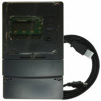
REF DESIGN MCP3909 3PH ENGY MTR
Manufacturer
Microchip Technology
Datasheets
1.MCP3909T-ISS.pdf
(44 pages)
2.MCP3909T-ISS.pdf
(104 pages)
3.MCP3909RD-3PH3.pdf
(88 pages)
Specifications of MCP3909RD-3PH1
Main Purpose
Power Management, Energy/Power Meter
Embedded
No
Utilized Ic / Part
MCP3909, PIC18F2520, PIC18F4550
Primary Attributes
3-Ph, 220 VAC, In Case, LCD, USB, GUI
Secondary Attributes
Opto-Isolated Interface for Safety
Operating Voltage
220 V
Operating Current
5 A
Description/function
Energy Meter
For Use With/related Products
MCP3909
Lead Free Status / RoHS Status
Not applicable / Not applicable


MCP3909 3-Phase Energy Meter Reference Design
6.8
DS51643B-page 60
METER CALIBRATION
One of the main functions of the software is to assist in meter calibration. This process
is accomplished by selecting the phase for calibration and clicking the “CALIBRATE”
button. The following steps will occur for a given phase:
1. Calibrate phase under configuration C1 as either a standard phase or a
2. Calibrate phase under configuration C2 for phase delay.
3. Calibrate phase under configuration C3 for active power offset.
4. Calibrate phase under configuration C4 for RMS offset.
For a meter to be entirely calibrated, all 3 phases must be calibrated separately, with
one of the phases being selected as the standard phase.
6.8.1
The first step is to apply VCAL and ICAL to a given phase and choose whether or not
this phase is being selected as the standard phase. The software will prompt the user
with this question and also instruct the user to apply the correct voltages and currents.
The software calculates the calibration registers through the equations defined in
Chapter 5. “Meter Calibration” and allows the user to input the exact voltages and
current for more correct calibration register numbers.
The following dialog window will appear in configuration C1:
FIGURE 6-3:
At this point, the software will default to the VCAL and ICAL values that are currently in
the meter design frame. The user can MODIFY these values to the exact currents and
voltages that are being read from the calibrated meter equipment present during
calibration. In the example above, the user modified the numbers 220 to be 220.23V
and 10A to be 10.15A.
Once the user selects the “OK” button, energy accumulation will occur and status can
be observed via the energy accumulation bar.
Section 5.3.3 and Section 5.3.5 describes the registers and equations that the soft-
ware uses to calibrate the meter.
non-standard phase.
Calibration Step 1 - Configuration C1
Calibration Step C1 with calibration settings input boxes.
© 2008 Microchip Technology Inc.
Related parts for MCP3909RD-3PH1
Image
Part Number
Description
Manufacturer
Datasheet
Request
R

Part Number:
Description:
BOARD DES MCP3909 ENERGY METER
Manufacturer:
Microchip Technology
Datasheet:

Part Number:
Description:
REF DESIGN FOR MCP3909 W/18F2520
Manufacturer:
Microchip Technology
Datasheet:

Part Number:
Description:
Manufacturer:
Microchip Technology Inc.
Datasheet:
Part Number:
Description:
Manufacturer:
Microchip Technology Inc.
Datasheet:
Part Number:
Description:
Manufacturer:
Microchip Technology Inc.
Datasheet:
Part Number:
Description:
Manufacturer:
Microchip Technology Inc.
Datasheet:
Part Number:
Description:
Manufacturer:
Microchip Technology Inc.
Datasheet:
Part Number:
Description:
Manufacturer:
Microchip Technology Inc.
Datasheet:
Part Number:
Description:
Manufacturer:
Microchip Technology Inc.
Datasheet:
Part Number:
Description:
Manufacturer:
Microchip Technology Inc.
Datasheet: