MCP3909EV-MCU16 Microchip Technology, MCP3909EV-MCU16 Datasheet - Page 22
MCP3909EV-MCU16
Manufacturer Part Number
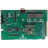
MCP3909EV-MCU16
Description
EVALUATION BOARD FOR MCP3909
Manufacturer
Microchip Technology
Datasheets
1.MCP3909T-ISS.pdf
(44 pages)
2.MCP3909T-ISS.pdf
(104 pages)
3.MCP3909EV-MCU16.pdf
(38 pages)
Specifications of MCP3909EV-MCU16
Number Of Adc's
2
Number Of Bits
16
Sampling Rate (per Second)
15k
Data Interface
Serial
Inputs Per Adc
1 Differential
Input Range
±1 V
Voltage Supply Source
Analog and Digital
Operating Temperature
-40°C ~ 85°C
Utilized Ic / Part
MCP3909
Silicon Manufacturer
Microchip
Application Sub Type
ADC
Kit Application Type
Data Converter
Silicon Core Number
MCP3909
Kit Contents
Board
Lead Free Status / RoHS Status
Lead free / RoHS Compliant


MCP3909 / dsPIC33F 3-Phase Energy Meter Reference Design
2.4
TABLE 2-1:
DS51723A-page 22
62, 1
2, 3
13, 12 RB3, RB4
14
15
16
4, 5, 6 SCK, SDI, SDO
42
49-51
61
53
36, 37 SDA1 / SCL1
33, 34 U1TX / U1RX
33, 34,
35
27
28
17, 18 ICSPCLK, ICSP-
7
dsPIC
Pin
DSPIC33F HARDWARE CONNECTION AND PERIPHERAL USAGE
RG14, RG15
RC1, RC2
RB2
RB1
RB0
INT1
RD1-RD3
RG0
RC13, RC14
SDO1/SDI1/SCK1
AN12
AN13
DAT
MCLR
Pin Function
Name
FUNCTIONAL ALLOCATION FOR dsPIC33F PINS
Table 2-1 is the pin allocation for the dsPIC33FJ64GP206 MCU.
G0A, G1A
G0B, G1B
G0C, G1C
CSA
CSB
CSC
PULSE1, PULSE2,
PULSE3
RF3/RF2/RF6
Current_N
Ref_V
ICSP I/F
MCLR
Corresponding Name
SPI I/F
SDO
AD_MCLR
LED1, LED2
SDA/SCL
RF3/RF2
in Schematic
Diagram
MCP3909's gain control for Phase A
MCP3909's gain control for Phase B
MCP3909's gain control for Phase C
MCP3909's chip-select signal corresponding to Phase A
MCP3909's chip-select signal corresponding to Phase B
MCP3909's chip-select signal corresponding to Phase C
Interface signal of SPI2. SPI interface operates under master
mode, used for the MCP3909 device communications
SDO line of SPI interface, for detecting MCP3909's A/D
conversion complete flag
PULSE1 is total phase active power pulse output, PULSE2 is
total phase reactive power pulse output. PULSE3's function is
to be determined.
Master clear signal of 3 MCP3909 devices (tied together)
LED drive pins, can be used as energy pulse output indicator,
for meter calibration. Its function is similar to those of
PULSE1 and PULSE2
I
UART interface
SPI1 interface, can be designed by customers, used for
communication with host MCU to obtain measurement results
and calibrate a meter. Its function is the same as UART
interface, but have a faster communication rate and higher
efficiency. SPI operates in slave mode. If UART interface is
used to communicate with host MCU, then this interface
cannot be used.
Detect neutral current
Detect boost voltage of neutral current
Online debugging/programming interface
Master clear input
2
C™ interface, used to read/write EEPROM externally
Functional Description
© 2009 Microchip Technology Inc.
Related parts for MCP3909EV-MCU16
Image
Part Number
Description
Manufacturer
Datasheet
Request
R

Part Number:
Description:
Manufacturer:
Microchip Technology Inc.
Datasheet:
Part Number:
Description:
Manufacturer:
Microchip Technology Inc.
Datasheet:
Part Number:
Description:
Manufacturer:
Microchip Technology Inc.
Datasheet:
Part Number:
Description:
Manufacturer:
Microchip Technology Inc.
Datasheet:
Part Number:
Description:
Manufacturer:
Microchip Technology Inc.
Datasheet:
Part Number:
Description:
Manufacturer:
Microchip Technology Inc.
Datasheet:
Part Number:
Description:
Manufacturer:
Microchip Technology Inc.
Datasheet:
Part Number:
Description:
Manufacturer:
Microchip Technology Inc.
Datasheet: