MCP3909EV-MCU16 Microchip Technology, MCP3909EV-MCU16 Datasheet - Page 23
MCP3909EV-MCU16
Manufacturer Part Number
MCP3909EV-MCU16
Description
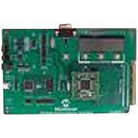
EVALUATION BOARD FOR MCP3909
Manufacturer
Microchip Technology
Datasheets
1.MCP3909T-ISS.pdf
(44 pages)
2.MCP3909T-ISS.pdf
(104 pages)
3.MCP3909EV-MCU16.pdf
(38 pages)
Specifications of MCP3909EV-MCU16
Number Of Adc's
2
Number Of Bits
16
Sampling Rate (per Second)
15k
Data Interface
Serial
Inputs Per Adc
1 Differential
Input Range
±1 V
Voltage Supply Source
Analog and Digital
Operating Temperature
-40°C ~ 85°C
Utilized Ic / Part
MCP3909
Silicon Manufacturer
Microchip
Application Sub Type
ADC
Kit Application Type
Data Converter
Silicon Core Number
MCP3909
Kit Contents
Board
Lead Free Status / RoHS Status
Lead free / RoHS Compliant


© 2009 Microchip Technology Inc.
2.4.1
The UART and SPI1 interfaces are multiplexed. Through the UART or SPI1 interface,
the host MCU can communicate with the metering front-end to perform calibration or
obtain metering results. The SPI interface may also be used if high-speed data transfer
is desired. In this case, the SPI interface of the dsPIC device works in the slave mode.
The UART and SPI1 share a common pin, so only one of the two interfaces can be
used at a time. Since the reference design uses a PC to simulate the host MCU, the
UART interface is chosen as the communication interface. SPI and RS232 interfaces
are not isolated from the PC. A general-purpose transceiver device, MAX232, is used
for the UART interface.
2.4.2
Three sets of outputs for energy measurement pulses are available in this design,
corresponding to the I/O pins of RD1-RD3. Two of them, output total active energy and
total reactive energy, respectively, and the other is not yet specified. Outputs are
isolated by a photo-electronic coupling device, U
active when corresponding I/O pin is high.
In addition, the design also provides two sets of LED outputs for energy meter calibra-
tion. The output pins for these LEDs are RC13 and RC14. The LED is on when the
output is low. Figure 2-4 is the circuit of energy pulse output interface.
FIGURE 2-4:
Energy Pulse Output Interface
RD3
RD1
UART and SPI1 Interface
RD2
RC13
RC14
Energy Output Pulse Configuration.
1 kΩ
R
1 kΩ
R
1 kΩ
R
301
301
301
R
470Ω
R
470Ω
314
310
Hardware Description
3.3V
3.3V
3
. The photo-electronic coupler is
D303
D302
Total Reactive
(not used)
Total Active
Total Reactive
Total Active
DS51723A-page 23
Related parts for MCP3909EV-MCU16
Image
Part Number
Description
Manufacturer
Datasheet
Request
R

Part Number:
Description:
Manufacturer:
Microchip Technology Inc.
Datasheet:
Part Number:
Description:
Manufacturer:
Microchip Technology Inc.
Datasheet:
Part Number:
Description:
Manufacturer:
Microchip Technology Inc.
Datasheet:
Part Number:
Description:
Manufacturer:
Microchip Technology Inc.
Datasheet:
Part Number:
Description:
Manufacturer:
Microchip Technology Inc.
Datasheet:
Part Number:
Description:
Manufacturer:
Microchip Technology Inc.
Datasheet:
Part Number:
Description:
Manufacturer:
Microchip Technology Inc.
Datasheet:
Part Number:
Description:
Manufacturer:
Microchip Technology Inc.
Datasheet: