MCP3909EV-MCU16 Microchip Technology, MCP3909EV-MCU16 Datasheet - Page 32
MCP3909EV-MCU16
Manufacturer Part Number
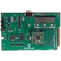
MCP3909EV-MCU16
Description
EVALUATION BOARD FOR MCP3909
Manufacturer
Microchip Technology
Datasheets
1.MCP3909T-ISS.pdf
(44 pages)
2.MCP3909T-ISS.pdf
(104 pages)
3.MCP3909EV-MCU16.pdf
(38 pages)
Specifications of MCP3909EV-MCU16
Number Of Adc's
2
Number Of Bits
16
Sampling Rate (per Second)
15k
Data Interface
Serial
Inputs Per Adc
1 Differential
Input Range
±1 V
Voltage Supply Source
Analog and Digital
Operating Temperature
-40°C ~ 85°C
Utilized Ic / Part
MCP3909
Silicon Manufacturer
Microchip
Application Sub Type
ADC
Kit Application Type
Data Converter
Silicon Core Number
MCP3909
Kit Contents
Board
Lead Free Status / RoHS Status
Lead free / RoHS Compliant


MCP3909 / dsPIC33F 3-Phase Energy Meter Reference Design
DS51723A-page 32
3.3.6
Energy accumulation is done by calculating the total energy, which is the algebraic sum
of energy of each phase. Active energy is obtained by accumulating the multiplication
of voltage and current of each sample, which ensures the high accuracy of measure-
ment.
3.3.7
The required measurement accuracy of reactive energy low, so in this design, it is
obtained by accumulating the product of the present measured reactive power and the
time interval between two measurements.
3.3.8
Refer to Section 2.4.2 “Energy Pulse Output Interface” for pulse output. To ensure
the uniformity of output pulses, the calculation is divided in the measurement cycle into
in a number of equal sections, and accumulate them. For simplification and lowering
computation complexity, a counter is used to substitute the process of accumulation.
The counter is only enabled when accumulated energy approaches to the threshold of
the pulse output.
3.3.9
Frequency calculation is based on Equation C-52 and Equation C-53, in Appendix
C. “Power Calculation Theory”. The dsPIC33F collects 3-line cycles worth of data.
The first two cycles of data of all sampled data is analyzed, and then the frequency of
two successive cycles is used.
The data of two successive cycles are transformed via DFT for the fundamental, which
is accomplished by assemble function DFT_Fundamental(). This is followed by the
computation of the initial phase angle of the first two line cycles. Then the phase lag
and frequency offset of the two line cycles of signal can be calculated.
When measuring frequency, only the first two cycles of data are used. It must be
assumed the input frequency is 50 Hz and the chosen appropriate sine/cosine table to
carry out DFT transform for fundamentals of the 1st and 2nd cycles of data. See
Appendix D. “50/60 Hz Meter Operation” for 60 Hz firmware.
Frequency offset is calculated by determining the initial phase angle for each line cycle.
The greater the frequency offset, the greater the measurement error.
Since one of the 3 phases may be missing, if the voltage magnitude for phase A is less
than the threshold, it is necessary to switch to phase B. Consequently, if sufficient volt-
age magnitude of phase B is not detected, it is necessary to switch to phase C.
The basic algorithm for measuring line frequency is based on the method described in
Appendix A, Section C.4 “Measuring The Voltage/current Rms Value And Power
Using Quasi-synchronous Sampling Algorithm”.
Frequency will be measured once for every 3 times the data is sampled.
Active Energy Accumulation
Reactive Energy Accumulation
Output Pulse Generation
Line Frequency Calculation
© 2009 Microchip Technology Inc.
Related parts for MCP3909EV-MCU16
Image
Part Number
Description
Manufacturer
Datasheet
Request
R

Part Number:
Description:
Manufacturer:
Microchip Technology Inc.
Datasheet:
Part Number:
Description:
Manufacturer:
Microchip Technology Inc.
Datasheet:
Part Number:
Description:
Manufacturer:
Microchip Technology Inc.
Datasheet:
Part Number:
Description:
Manufacturer:
Microchip Technology Inc.
Datasheet:
Part Number:
Description:
Manufacturer:
Microchip Technology Inc.
Datasheet:
Part Number:
Description:
Manufacturer:
Microchip Technology Inc.
Datasheet:
Part Number:
Description:
Manufacturer:
Microchip Technology Inc.
Datasheet:
Part Number:
Description:
Manufacturer:
Microchip Technology Inc.
Datasheet: