MCP3909EV-MCU16 Microchip Technology, MCP3909EV-MCU16 Datasheet - Page 30
MCP3909EV-MCU16
Manufacturer Part Number
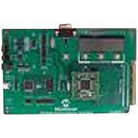
MCP3909EV-MCU16
Description
EVALUATION BOARD FOR MCP3909
Manufacturer
Microchip Technology
Datasheets
1.MCP3909T-ISS.pdf
(44 pages)
2.MCP3909T-ISS.pdf
(104 pages)
3.MCP3909EV-MCU16.pdf
(38 pages)
Specifications of MCP3909EV-MCU16
Number Of Adc's
2
Number Of Bits
16
Sampling Rate (per Second)
15k
Data Interface
Serial
Inputs Per Adc
1 Differential
Input Range
±1 V
Voltage Supply Source
Analog and Digital
Operating Temperature
-40°C ~ 85°C
Utilized Ic / Part
MCP3909
Silicon Manufacturer
Microchip
Application Sub Type
ADC
Kit Application Type
Data Converter
Silicon Core Number
MCP3909
Kit Contents
Board
Lead Free Status / RoHS Status
Lead free / RoHS Compliant


MCP3909 / dsPIC33F 3-Phase Energy Meter Reference Design
DS51723A-page 30
Each block can be categorized into one of three types of calculations:
1. Calculation for an individual phase
2. Calculation for all 3 phases
3. Calculation of power accumulation (Energy)
3.3.1
The first blocks of the calculation flow are to determine how many samples to use for
the quasi-synchronization sampling algorithm. See Appendix C. “Power Calculation
Theory” for more information on this approach.
The firmware selects the proper quasi-synchronization window function (array of data)
and corresponding sine/cosine table according to the number of sampling points in
present current cycle.
The number of sampling points is obtained from the last calculation of frequency
function. As the line frequency fluctuates in slow motion and typically varies by a small
amount over three (3) line cycles, the period of line frequency measurements of the
previous cycle can be used to determine data length of sampling.
The quasi-synchronization window function is an array established in advance, and its
length is the same as that of the sampling data, which is obtained by the weight
coefficient multiplied by 32768. In this design, the method of quadrature by
complexification echelon is used, corresponding weight coefficient is calculated with
three (3) iterations. Three iterations implies that the length of the input original data is
equal to the number of sampling points in three cycles. The number of sampling points
in each cycle is usually different from the input signal cycle, but it will be close to an
integral multiple of the input signal cycle. For example, at a sampling rate of 3.2 ksps,
50 Hz input signal corresponds to 64 sampling points for each cycle, and 50.1 Hz input
signal would also be close to 64 sampling points for each cycle. Again, 51 Hz input
signal would be close to 63 sampling points for each cycle. Therefore, at different input
frequencies, the corresponding numbers of sampling points in each cycle are different.
Consequently, the corresponding quasi-sync window function and sine/cosine table
need to be established according to different numbers of sampling points. The
sine/cosine table is established by evenly dividing a cycle into a number of segments
equal to the number of sampling points, calculating corresponding sine/cosine values
and then multiplying the values by 32768. The purpose of the multiplication is to
change the original operation of floating point numbers into that of fixed-point numbers.
Adjustments will be performed in the final stage of calculation.
The processing of the original signal being processed by the quasi-synchronization
window function is actually a process of array multiplication, i.e. the original input signal
is multiplied with a corresponding array of window functions. It's accomplished by the
function qusi_syn_wnd(), which is written in assembly to take full advantages of DSP
features.
3.3.2
A Direct Fourier Transform (DFT) is performed on the collected sets of data. Process-
ing of the original signal by quasi-synchronization window can effectively reduce
spectrum leakage caused by non-entire-cycle sampling during DFT transformation.
The data length is not a power of 2, therefore, the FFT algorithm cannot be used in DFT
transformation. DFT transform is accomplished by function DFT(), which is written in
assembly to take full advantages of the DSP feature of accumulated multiplication.
Since an FFT algorithm cannot be used, and it takes longer to perform a DFT
calculation, this is the most time-consuming process in the entire system.
Process Quasi-Synchronization Window
DFT Transformation
© 2009 Microchip Technology Inc.
Related parts for MCP3909EV-MCU16
Image
Part Number
Description
Manufacturer
Datasheet
Request
R

Part Number:
Description:
Manufacturer:
Microchip Technology Inc.
Datasheet:
Part Number:
Description:
Manufacturer:
Microchip Technology Inc.
Datasheet:
Part Number:
Description:
Manufacturer:
Microchip Technology Inc.
Datasheet:
Part Number:
Description:
Manufacturer:
Microchip Technology Inc.
Datasheet:
Part Number:
Description:
Manufacturer:
Microchip Technology Inc.
Datasheet:
Part Number:
Description:
Manufacturer:
Microchip Technology Inc.
Datasheet:
Part Number:
Description:
Manufacturer:
Microchip Technology Inc.
Datasheet:
Part Number:
Description:
Manufacturer:
Microchip Technology Inc.
Datasheet: