MCP3909EV-MCU16 Microchip Technology, MCP3909EV-MCU16 Datasheet - Page 40
MCP3909EV-MCU16
Manufacturer Part Number
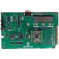
MCP3909EV-MCU16
Description
EVALUATION BOARD FOR MCP3909
Manufacturer
Microchip Technology
Datasheets
1.MCP3909T-ISS.pdf
(44 pages)
2.MCP3909T-ISS.pdf
(104 pages)
3.MCP3909EV-MCU16.pdf
(38 pages)
Specifications of MCP3909EV-MCU16
Number Of Adc's
2
Number Of Bits
16
Sampling Rate (per Second)
15k
Data Interface
Serial
Inputs Per Adc
1 Differential
Input Range
±1 V
Voltage Supply Source
Analog and Digital
Operating Temperature
-40°C ~ 85°C
Utilized Ic / Part
MCP3909
Silicon Manufacturer
Microchip
Application Sub Type
ADC
Kit Application Type
Data Converter
Silicon Core Number
MCP3909
Kit Contents
Board
Lead Free Status / RoHS Status
Lead free / RoHS Compliant


MCP3909 / dsPIC33F 3-Phase Energy Meter Reference Design
4.3
DS51723A-page 40
APPARENT POWER CALIBRATION
4.2.1
The process of calibration is as follows:
1. Supply the meter with balanced load, PF = 1.0, V
2. Load the dsPIC33F with the proper correction factors. Automatically done using
Repeat these following steps for the second point at 10% IB:
1.
2. Load the dsPIC33F with the proper correction factors. Automatically done using
If accuracy is not critical, the single-point calibration method can be used. The number
of calibration points can be defined in the header file of the program.
Apparent Power calibration function is implemented by the upper computer by sending
the commands. Before the power calibration process can be entered, power calibration
mode command needs to be sent first. The error data of the calibration workbench and
channel information to be calibrated are sent to the metering front-end. When the
front-end receives the command, it calls this module. The flow is as follows:
1. Determine the phase to be calibrated according to the parameters received.
2. Calculate new power calibration coefficient according to the error value received
3. Store the coefficient after correction into the EEPROM.
4.3.1
The process of calibration is as follows:
1. Set the input condition as: Phase A PF = 1.0, V
2. Choose the energy pulse output to be the apparent power output mode Refer to
3. Load the dsPIC33F with the proper correction factors. This is automatically done
4.
5. Repeat the above steps for Phases B and C.
Note:
the PC software. See Chapter 5. “PC Software”.
Set the three-phase balance input conditions
500 mA.
the PC software. See Chapter 5. “PC Software”.
and the measured value, together with the original power calibration coefficient.
current when region N is being calibrated, the voltage and current inputs of phase
B and C are zero.
Chapter 6. “Meter Communications Protocol”. At this time, the energy pulse
is the accumulated multiplication of power and time.
using PC software. See Chapter 5. “PC Software”.
Repeat steps 1 - 3 for phase lag calibrations for all current regions of phase A.
Current/Voltage Calibration Process
Apparent Power Calibration Process
At this time, the phase lag has not been calibrated, so when the input
PF = 1.0, the measured value of the reactive power isn't equal to zero.
PF = 1.0, V
CAL
CAL
= 220V, input current is the
CAL
= 220V, I
© 2009 Microchip Technology Inc.
= 220V, I
B
= 5A.
CAL
= 0.1 I
B
or
Related parts for MCP3909EV-MCU16
Image
Part Number
Description
Manufacturer
Datasheet
Request
R

Part Number:
Description:
Manufacturer:
Microchip Technology Inc.
Datasheet:
Part Number:
Description:
Manufacturer:
Microchip Technology Inc.
Datasheet:
Part Number:
Description:
Manufacturer:
Microchip Technology Inc.
Datasheet:
Part Number:
Description:
Manufacturer:
Microchip Technology Inc.
Datasheet:
Part Number:
Description:
Manufacturer:
Microchip Technology Inc.
Datasheet:
Part Number:
Description:
Manufacturer:
Microchip Technology Inc.
Datasheet:
Part Number:
Description:
Manufacturer:
Microchip Technology Inc.
Datasheet:
Part Number:
Description:
Manufacturer:
Microchip Technology Inc.
Datasheet: