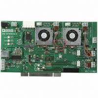
EVAL-ADT7467EB Analog Devices Inc, EVAL-ADT7467EB Datasheet - Page 29

EVAL-ADT7467EB
Manufacturer Part Number
EVAL-ADT7467EB
Description
BOARD EVALUATION FOR ADT7467
Manufacturer
Analog Devices Inc
Series
dBCool®r
Datasheet
1.EVAL-ADT7467EB.pdf
(80 pages)
Specifications of EVAL-ADT7467EB
Sensor Type
Temperature
Sensing Range
-40°C ~ 120°C
Interface
SMBus (2-Wire/I²C)
Sensitivity
±1.5°C
Voltage - Supply
3 V ~ 5.5 V
Embedded
No
Utilized Ic / Part
ADT7467
Lead Free Status / RoHS Status
Contains lead / RoHS non-compliant
Note that when the voltage spikes (either negative going or
positive going) are more than 40 mV in amplitude, the fan
speed can be reliably determined.
LAYING OUT 2-WIRE AND 3-WIRE FANS
Figure 41 shows how to lay out a common circuit arrangement
for 2-wire and 3-wire fans. Some components are not
populated, depending on whether a 2-wire or 3-wire fan is used.
ADT7467
TACH
Figure 40. Fan Speed Sensing Waveform at TACH/AIN Pin
Figure 41. Planning for 2-Wire or 3-Wire Fans on a PCB
TACH
PWM
R1
R2
R3
Figure 39. Driving a 2-Wire Fan
3.3V
12V OR 5V
C1
10kΩ
TYPICAL
R4
0.01μF
Q1
MMBT2222
12V FAN
5V OR
1N4148
FOR 3-WIRE FANS:
POPULATE R1, R2, R3
R4 = 0W
C1 = UNPOPULATED
FOR 2-WIRE FANS:
POPULATE R4, C1
R1, R2, R3 UNPOPULATED
R5
3.3V OR 5V
+V
PWM
Q1
NDT3055L
R
2Ω
TYPICAL
SENSE
1N4148
Rev. A| Page 29 of 80
TACH Inputs
When configured as TACH inputs, Pins 4, 6, 7, and 9 are open-
drain TACH inputs intended for fan speed measurement.
Signal conditioning in the ADT7467 accommodates the slow
rise and fall times typical of fan tachometer outputs. The
maximum input signal range is 0 V to 5 V, even when V
than 5 V. In the event that these inputs are supplied from fan
outputs that exceed 0 V to 5 V, either resistive attenuation of the
fan signal or diode clamping must be included to keep inputs
within an acceptable range.
Figure 42 to Figure 45 show circuits for most common fan
TACH outputs. If the fan TACH output has a resistive pull-up
to V
Figure 42.
If the fan output has a resistive pull-up to 12 V (or another
voltage that is greater than 5 V), the fan output can be clamped
with a Zener diode, as shown in Figure 43. The Zener diode
voltage should be chosen so that it is greater than the V
TACH input but less than 5 V, allowing for the voltage tolerance
of the Zener. A value between 3 V and 5 V is suitable.
If the fan has a strong pull-up (less than 1 kΩ) to 12 V or a
totem-pole output, a series resistor can be added to limit the
Zener current, as shown in Figure 44.
Figure 43. Fan with TACH Pull-Up to a Voltage >5 V (for example, 12 V),
CC
12V
, it can be connected directly to the fan input, as shown in
12V
*CHOOSE ZD1 VOLTAGE APPROXIMATELY 0.8 × V
PULL-UP
TYPICAL
PULL-UP
TYPICAL
Figure 42. Fan with TACH Pull-Up to V
4.7kΩ
4.7kΩ
Clamped with Zener Diode
TACH
OUTPUT
TACH
OUTPUT
TACH
ZD1*
TACH
FAN SPEED
ADT7467
COUNTER
V
FAN SPEED
ADT7467
CC
COUNTER
CC
V
CC
ADT7467
CC
IH
CC
of the
is less


