EVAL-ADT7467EB Analog Devices Inc, EVAL-ADT7467EB Datasheet - Page 54
EVAL-ADT7467EB
Manufacturer Part Number
EVAL-ADT7467EB
Description
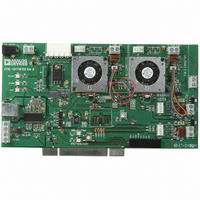
BOARD EVALUATION FOR ADT7467
Manufacturer
Analog Devices Inc
Series
dBCool®r
Datasheet
1.EVAL-ADT7467EB.pdf
(80 pages)
Specifications of EVAL-ADT7467EB
Sensor Type
Temperature
Sensing Range
-40°C ~ 120°C
Interface
SMBus (2-Wire/I²C)
Sensitivity
±1.5°C
Voltage - Supply
3 V ~ 5.5 V
Embedded
No
Utilized Ic / Part
ADT7467
Lead Free Status / RoHS Status
Contains lead / RoHS non-compliant


ADT7467
Enabling the THERM Trip Point as the Operating Point
Bits <4:2> of the dynamic T
enable/disable THERM monitoring to program the operating
point.
Dynamic T
<2> PHTR2 = 1 copies the Remote 2 current temperature to the
Remote 2 operating point register if THERM is asserted. The
operating point contains the temperature at which THERM is
asserted. This allows the system to run as quietly as possible
without affecting system performance.
PHTR2 = 0 ignores THERM assertions. The Remote 2
operating point register reflects its programmed value.
<3> PHTL = 1 copies the local current temperature to the local
temperature operating point register if THERM is asserted. The
operating point contains the temperature at which THERM is
asserted. This allows the system to run as quietly as possible
without affecting system performance.
PHTL = 0 ignores THERM assertions. The local temperature
operating point register reflects its programmed value.
<4> PHTR1 = 1 copies the Remote 1 current temperature to the
Remote 1 operating point register if THERM is asserted. The
operating point contains the temperature at which THERM is
asserted. This allows the system to run as quietly as possible
without affecting system performance.
PHTR1 = 0 ignores THERM assertions. The Remote 1
operating point register reflects its programmed value.
Enabling Dynamic T
Bits <7:5> of the dynamic T
enable/disable dynamic T
channels.
Dynamic T
<5> R2T = 1 enables the dynamic T
temperature channel. The chosen T
adjusted based on the current temperature, operating point, and
high and low limits for this zone.
R2T = 0 disables dynamic T
is not adjusted, and the channel behaves as described in the
section.
<6> LT = 1 enables dynamic T
temperature channel. The chosen T
adjusted based on the current temperature, operating point, and
high and low limits for this zone.
LT = 0 disables dynamic T
not adjusted, and the channel behaves as described in the
section.
MIN
MIN
Control Register 1 (0x36)
Control Register 1 (0x36)
MIN
MIN
Control Mode
MIN
MIN
MIN
MIN
control on the temperature
control. The T
MIN
control Register 1 (Reg. 0x36)
control Register 1 (Reg. 0x36)
control. The T
control on the local
MIN
MIN
MIN
value is dynamically
value is dynamically
control on the Remote 2
MIN
MIN
value chosen is
value chosen
Rev. A | Page 54 of 80
<7> R1T = 1 enables dynamic T
temperature channel. The chosen T
adjusted based on the current temperature, operating point, and
high and low limits for this zone.
R1T = 0 disables dynamic T
is not adjusted, and the channel behaves as described in the
Automatic Fan Control Overview section.
STEP 12: RAMP RATE FOR ACOUSTIC
ENHANCEMENT
The optimal ramp rate for acoustic enhancement can be
determined through system characterization after completing
the thermal optimization. If possible, the effect of each ramp
rate should be logged to determine the best setting for a given
solution.
Enhanced Acoustics Register 1 (Reg. 0x62)
<2:0> ACOU selects the ramp rate for PWM1.
Enhance Acoustics Register 2 (Reg. 0x63)
<2:0> ACOU3 selects the ramp rate for PWM3.
<6:4> ACOU2 selects the ramp rate for PWM2.
Another way to view the ramp rates is as the time it takes for the
PWM output to ramp up from 0% to 100% duty cycle for an
000 = 1 time slot = 35 sec
001 = 2 time slots = 17.6 sec
010 = 3 time slots = 11.8 sec
011 = 5 time slots = 7 sec
100 = 8 time slots = 4.4 sec
101 = 12 time slots =3 sec
110 = 24 time slots = 1.6 sec
111 = 48 time slots = 0.8 sec
000 = 1 time slot = 35 sec
001 = 2 time slots = 17.6 sec
010 = 3 time slots = 11.8 sec
011 = 5 time slots = 7 sec
100 = 8 time slots = 4.4 sec
101 = 12 time slots = 3 sec
110 = 24 time slots = 1.6 sec
111 = 48 time slots = 0.8 sec
000 = 1 time slot = 35 sec
001 = 2 time slots = 17.6 sec
010 = 3 time slots = 11.8 sec
011 = 5 time slots = 7 sec
100 = 8 time slots = 4.4 sec
101 = 12 time slots = 3 sec
110 = 24 time slots = 1.6 sec
111 = 48 time slots = 0.8 sec
MIN
control. The T
MIN
control on the Remote 1
MIN
value is dynamically
MIN
value chosen
Related parts for EVAL-ADT7467EB
Image
Part Number
Description
Manufacturer
Datasheet
Request
R


Part Number:
Description:
BOARD EVAL FOR SI270X-A
Manufacturer:
Silicon Laboratories Inc
Datasheet:

Part Number:
Description:
BUCK CONV REF DESIGN KIT IP1201
Manufacturer:
International Rectifier
Datasheet:
Part Number:
Description:
BOARD DEMO SYNC DUAL BUCK CNVTER
Manufacturer:
International Rectifier
Datasheet:
Part Number:
Description:
BOARD DEMO SYNC BUCK CONVETER
Manufacturer:
International Rectifier
Datasheet:

Part Number:
Description:
EVALBOARD/EB Omnidirectional microphone - Analog
Manufacturer:
Analog Devices
Datasheet:
Part Number:
Description:
EVALBOARD/EB Omnidirectional microphone - Analog
Manufacturer:
Analog Devices
Datasheet:


Part Number:
Description:
BOARD EVAL LED DRIVER LT3756
Manufacturer:
Linear Technology
Datasheet:

Part Number:
Description:
BOARD EVAL FOR AD7741/7742
Manufacturer:
Analog Devices Inc
Datasheet:

Part Number:
Description:
±1.7g Dual-Axis IMEMS Accelerometer Evaluation Board
Manufacturer:
Analog Devices Inc
Datasheet:

Part Number:
Description:
IC MULTIPLIER ANALOG 8-SOIC T/R
Manufacturer:
Analog Devices Inc
Datasheet:

Part Number:
Description:
IC ANALOG MULTIPLIER 8-DIP
Manufacturer:
Analog Devices Inc
Datasheet:
Part Number:
Description:
IC ANALOG MULTIPLIER 8-SOIC
Manufacturer:
Analog Devices Inc
Datasheet:
Part Number:
Description:
IC ANALOG MULTIPLIER 8-DIP
Manufacturer:
Analog Devices Inc
Datasheet: