EVAL-ADT7467EB Analog Devices Inc, EVAL-ADT7467EB Datasheet - Page 32
EVAL-ADT7467EB
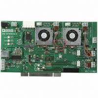
Manufacturer Part Number
EVAL-ADT7467EB
Description
BOARD EVALUATION FOR ADT7467
Manufacturer
Analog Devices Inc
Series
dBCool®r
Datasheet
1.EVAL-ADT7467EB.pdf
(80 pages)
Specifications of EVAL-ADT7467EB
Sensor Type
Temperature
Sensing Range
-40°C ~ 120°C
Interface
SMBus (2-Wire/I²C)
Sensitivity
±1.5°C
Voltage - Supply
3 V ~ 5.5 V
Embedded
No
Utilized Ic / Part
ADT7467
Lead Free Status / RoHS Status
Contains lead / RoHS non-compliant


ADT7467
Configuration Register 4 (Reg. 0x7D)
<3:2> AINL, input threshold for 2-wire fan speed
measurements
FAN SPIN-UP
The ADT7467 has a unique fan spin-up function. It spins the
fan at 100% PWM duty cycle until two TACH pulses are de-
tected on the TACH input. Then, the PWM duty cycle goes to
the expected running value, for example, 33%. The advantage is
that fans have different spin-up characteristics and take
different times to overcome inertia. The ADT7467 runs the fans
just fast enough to overcome inertia and is quieter during spin-
up than other fans programmed to spin up for a given spin-up
time.
Fan Start-Up Timeout
To prevent the generation of false interrupts as a fan spins up
(because it is below running speed), the ADT7467 includes a
fan start-up timeout function. During this time, the ADT7467
looks for two TACH pulses. If two TACH pulses are not detected,
an interrupt is generated. Using Configuration Register 4 (0x40)
Bit 5 (FSPDIS), the functionality of this bit can be changed (see
the Disabling Fan Start-Up Timeout section).
PWM1 Configuration (Reg. 0x5C)
<2:0> SPIN, start-up timeout for PWM1
PWM2 Configuration (Reg. 0x5D)
<2:0> SPIN, start-up timeout for PWM2
00 = ±20 mV
01 = ±40 mV
10 = ±80 mV
11 = ±130 mV
000 = no start-up timeout
001 = 100 ms
010 = 250 ms default
011 = 400 ms
100 = 667 ms
101 = 1 sec
110 = 2 sec
111 = 4 sec
000 = no start-up timeout
001 = 100 ms
010 = 250 ms default
011 = 400 ms
100 = 667 ms
Rev. A | Page 32 of 80
PWM3 Configuration (Reg. 0x5E)
<2:0> SPIN, start-up timeout for PWM3
Disabling Fan Start-Up Timeout
Although fan start-up makes fan spin-ups more quite than
fixed-time spin-ups, users can use fixed spin-up times. Setting
Bit 5 (FSPDIS) to 1 in Configuration Register 1 (Reg. 0x40)
disables the spin-up for two TACH pulses, and the fan spins up
for the fixed time selected in Reg. 0x5C to Reg. 0x5E.
PWM LOGIC STATE
The PWM outputs can be programmed high for 100% duty
cycle (noninverted) or programmed low for 100% duty cycle
(inverted).
PWM1 Configuration (Reg. 0x5C)
<4> INV
0 = logic high for 100% PWM duty cycle
1 = logic low for 100% PWM duty cycle
PWM2 Configuration (Reg. 0x5D)
<4> INV
0 = logic high for 100% PWM duty cycle
1 = logic low for 100% PWM duty cycle
PWM3 Configuration (Reg. 0x5E)
<4> INV
0 = logic high for 100% PWM duty cycle
1 = logic low for 100% PWM duty cycle
Low Frequency Mode PWM Drive Frequency
The PWM drive frequency can be adjusted for the application.
Reg. 0x5F to Reg. 0x61 configure the PWM frequency for
PWM1 to PWM3, respectively. In high frequency mode, the
PWM drive frequency is 22.5 kHz and cannot be changed.
101 = 1 sec
110 = 2 sec
111 = 4 sec
000 = no start-up timeout
001 = 100 ms
010 = 250 ms default
011 = 400 ms
100 = 667 ms
101 = 1 sec
110 = 2 sec
111 = 4 sec
Related parts for EVAL-ADT7467EB
Image
Part Number
Description
Manufacturer
Datasheet
Request
R


Part Number:
Description:
BOARD EVAL FOR SI270X-A
Manufacturer:
Silicon Laboratories Inc
Datasheet:

Part Number:
Description:
BUCK CONV REF DESIGN KIT IP1201
Manufacturer:
International Rectifier
Datasheet:
Part Number:
Description:
BOARD DEMO SYNC DUAL BUCK CNVTER
Manufacturer:
International Rectifier
Datasheet:
Part Number:
Description:
BOARD DEMO SYNC BUCK CONVETER
Manufacturer:
International Rectifier
Datasheet:

Part Number:
Description:
EVALBOARD/EB Omnidirectional microphone - Analog
Manufacturer:
Analog Devices
Datasheet:
Part Number:
Description:
EVALBOARD/EB Omnidirectional microphone - Analog
Manufacturer:
Analog Devices
Datasheet:


Part Number:
Description:
BOARD EVAL LED DRIVER LT3756
Manufacturer:
Linear Technology
Datasheet:

Part Number:
Description:
BOARD EVAL FOR AD7741/7742
Manufacturer:
Analog Devices Inc
Datasheet:

Part Number:
Description:
±1.7g Dual-Axis IMEMS Accelerometer Evaluation Board
Manufacturer:
Analog Devices Inc
Datasheet:

Part Number:
Description:
IC MULTIPLIER ANALOG 8-SOIC T/R
Manufacturer:
Analog Devices Inc
Datasheet:

Part Number:
Description:
IC ANALOG MULTIPLIER 8-DIP
Manufacturer:
Analog Devices Inc
Datasheet:
Part Number:
Description:
IC ANALOG MULTIPLIER 8-SOIC
Manufacturer:
Analog Devices Inc
Datasheet:
Part Number:
Description:
IC ANALOG MULTIPLIER 8-DIP
Manufacturer:
Analog Devices Inc
Datasheet: