EVAL-ADT7467EB Analog Devices Inc, EVAL-ADT7467EB Datasheet - Page 70
EVAL-ADT7467EB
Manufacturer Part Number
EVAL-ADT7467EB
Description
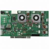
BOARD EVALUATION FOR ADT7467
Manufacturer
Analog Devices Inc
Series
dBCool®r
Datasheet
1.EVAL-ADT7467EB.pdf
(80 pages)
Specifications of EVAL-ADT7467EB
Sensor Type
Temperature
Sensing Range
-40°C ~ 120°C
Interface
SMBus (2-Wire/I²C)
Sensitivity
±1.5°C
Voltage - Supply
3 V ~ 5.5 V
Embedded
No
Utilized Ic / Part
ADT7467
Lead Free Status / RoHS Status
Contains lead / RoHS non-compliant


ADT7467
Table 36. Register 0x63—Enhanced Acoustics Register 2 (Power-On Default = 0x00)
Bit
<2:0>
< 3 >
<6:4>
<7>
1
Table 37. PWM Minimum Duty Cycle Registers
Register Address
0x64
0x65
0x66
Bit
<7:0>
1
Table 38. T
Register Address
0x67
0x68
0x69
1
2
This register becomes a read-only register when the Configuration Register 1 lock bit is set to 1. Any subsequent attempts to write to this register fail.
These registers become read-only registers when the ADT7467 is in automatic fan control mode.
These are the T
with temperature according to T
These registers become read-only registers when the Configuration Register 1 lock bit is set to 1. Any subsequent attempts to write to these registers fail.
Name
ACOU3
EN3
ACOU2
EN2
MIN
Name
PWM duty cycle
MIN
Registers
registers for each temperature channel. When the temperature measured exceeds T
R/W
Read/write
Read/write
Read/write
Read/write
1
1
RANGE
.
R/W
Read/write
Read/write
Read/write
R/W
Read/write
R/W
Read/write
Read/write
Read/write
Description
These bits select the ramp rate applied to the PWM3 output. Instead of PWM3 jumping instantaneously to
its newly calculated speed, PWM3 ramps gracefully at the rate determined by these bits. This effect
enhances the acoustics of the fan being driven by the PWM3 output.
Time Slot Increase
000 = 1
001 = 2
010 = 3
011 = 5
100 = 8
101 = 12
110 = 24
111 = 48
When this bit is 1, acoustic enhancement is enabled on PWM3 output.
These bits select the ramp rate applied to the PWM2 output. Instead of PWM2 jumping instantaneously to
its newly calculated speed, PWM2 ramps gracefully at the rate determined by these bits. This effect
enhances the acoustics of the fans being driven by the PWM2 output.
Time Slot Increase
000 = 1
001 = 2
010 = 3
011 = 5
100 = 8
101 = 12
110 = 24
When this bit is 1, acoustic enhancement is enabled on PWM2 output.
1
2
Description
PWM1 minimum duty cycle.
PWM2 minimum duty cycle.
PWM3 minimum duty cycle.
Description
These bits define the PWM
0x00 = 0% duty cycle (fan off).
0x40 = 25% duty cycle.
0x80 = 50% duty cycle.
0xFF = 100% duty cycle (fan full speed).
Description
Remote 1 temperature T
Local temperature T
Remote 2 temperature T
Rev. A | Page 70 of 80
Time for 33% to 100%
35 sec
17.6 sec
11.8 sec
7 sec
4.4 sec
3 sec
1.6 sec
0.8 sec
Time for 33% to 100%
35 sec
17.6 sec
11.8 sec
7 sec
4.4 sec
3 sec
1.6 sec
MIN
.
MIN
MIN
MIN
.
.
MIN
duty cycle for PWMx.
, the appropriate fan runs at minimum speed and increases
Power-On Default
0x80 (50% duty cycle)
0x80 (50% duty cycle)
0x80 (50% duty cycle)
Power-On Default
0x5A (90°C)
0x5A (90°C)
0x5A (90°C)
Related parts for EVAL-ADT7467EB
Image
Part Number
Description
Manufacturer
Datasheet
Request
R


Part Number:
Description:
BOARD EVAL FOR SI270X-A
Manufacturer:
Silicon Laboratories Inc
Datasheet:

Part Number:
Description:
BUCK CONV REF DESIGN KIT IP1201
Manufacturer:
International Rectifier
Datasheet:
Part Number:
Description:
BOARD DEMO SYNC DUAL BUCK CNVTER
Manufacturer:
International Rectifier
Datasheet:
Part Number:
Description:
BOARD DEMO SYNC BUCK CONVETER
Manufacturer:
International Rectifier
Datasheet:

Part Number:
Description:
EVALBOARD/EB Omnidirectional microphone - Analog
Manufacturer:
Analog Devices
Datasheet:
Part Number:
Description:
EVALBOARD/EB Omnidirectional microphone - Analog
Manufacturer:
Analog Devices
Datasheet:


Part Number:
Description:
BOARD EVAL LED DRIVER LT3756
Manufacturer:
Linear Technology
Datasheet:

Part Number:
Description:
BOARD EVAL FOR AD7741/7742
Manufacturer:
Analog Devices Inc
Datasheet:

Part Number:
Description:
±1.7g Dual-Axis IMEMS Accelerometer Evaluation Board
Manufacturer:
Analog Devices Inc
Datasheet:

Part Number:
Description:
IC MULTIPLIER ANALOG 8-SOIC T/R
Manufacturer:
Analog Devices Inc
Datasheet:

Part Number:
Description:
IC ANALOG MULTIPLIER 8-DIP
Manufacturer:
Analog Devices Inc
Datasheet:
Part Number:
Description:
IC ANALOG MULTIPLIER 8-SOIC
Manufacturer:
Analog Devices Inc
Datasheet:
Part Number:
Description:
IC ANALOG MULTIPLIER 8-DIP
Manufacturer:
Analog Devices Inc
Datasheet: