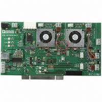
EVAL-ADT7467EB Analog Devices Inc, EVAL-ADT7467EB Datasheet - Page 53

EVAL-ADT7467EB
Manufacturer Part Number
EVAL-ADT7467EB
Description
BOARD EVALUATION FOR ADT7467
Manufacturer
Analog Devices Inc
Series
dBCool®r
Datasheet
1.EVAL-ADT7467EB.pdf
(80 pages)
Specifications of EVAL-ADT7467EB
Sensor Type
Temperature
Sensing Range
-40°C ~ 120°C
Interface
SMBus (2-Wire/I²C)
Sensitivity
±1.5°C
Voltage - Supply
3 V ~ 5.5 V
Embedded
No
Utilized Ic / Part
ADT7467
Lead Free Status / RoHS Status
Contains lead / RoHS non-compliant
Figure 74 shows how T
ture is above T
T
operating point. Once the temperature rises above the low
temperature limit, T
Preventing T
T
to reach full scale (127°C), because the fan would never switch
on. As a result, T
range:
1.
2.
3.
OPERATING
HIGH TEMP
LOW TEMP
MIN
MIN
THERM
The lowest possible value for T
complement mode) or −64°C (Offset 64 mode).
T
If the temperature is below T
runs at minimum speed and dynamic T
disabled.
is below the high temperature limit and below the
is dynamically adjusted; therefore, it is undesirable for T
POINT
LIMIT
LIMIT
LIMIT
MIN
T
MIN
cannot exceed the high temperature limit.
HYSTERESIS
Figure 74. Increasing T
ACTUAL
MIN
MIN
TEMP
MIN
from Reaching Full Scale
but below the low temperature limit, and how
MIN
is allowed to vary only within a specified
MIN
remains fixed.
increases when the current tempera-
OPERATING
HIGH TEMP
LOW TEMP
MIN
MIN
THERM
for Quiet Operation
POINT
LIMIT
LIMIT
LIMIT
MIN
T
, the fan switches off or
Figure 73. Effect of Exceeding Operating Point Minus Hysteresis Temperature
MIN
is –127°C (twos
HYSTERESIS
DECREASE HERE DUE TO
T1(n) – T1 (n – 1) = 0.5°C
EVERY SHORT CYCLE
MIN
SHORT CYCLE ONLY
DECREASES BY 1°C
OR 0.75°C = > T
control is
ACTUAL
TEMP
MIN
Rev. A| Page 53 of 80
MIN
DECREASE HERE DUE TO
T1(n) – T1 (n – 1) ≤ 0.25°C
AND T1(n) > OP = > T
EVERY LONG CYCLE
DECREASES BY 1°C
LONG CYCLE ONLY
STEP 11: MONITORING THERM
Using the operating point limit ensures that the dynamic T
control mode operates in the best possible acoustic position and
that the temperature never exceeds the maximum operating
temperature. Using the operating point limit allows T
independent of system-level issues because of its self-corrective
nature. In PC design, the operating point for the chassis is usually
the worst-case internal chassis temperature.
The optimal operating point for the processor is determined by
monitoring the thermal monitor in the Intel Pentium 4 proces-
sor. To do this, the PROCHOT output of the Pentium 4 is
connected to the THERM input of the ADT7467.
The operating point for the processor can be determined by
allowing the current temperature to be copied to the operating
point register when the PROCHOT output pulls the THERM
input low on the ADT7467. This reveals the maximum
temperature at which the Pentium 4 can run before clock
modulation occurs.
OPERATING
HIGH TEMP
LOW TEMP
THERM
Figure 75. T
POINT
LIMIT
LIMIT
LIMIT
T
MIN
DUE TO ANY CYCLE, BECAUSE
MIN
NO CHANGE IN T
T1(n) – T1 (n – 1) ≤ 0.25°C
AND T1(n) < OP = > T
HYSTERESIS
STAYS THE SAME
MIN
ACTUAL
TEMP
Adjustments Limited by the High Temperature Limit
MIN
HERE
MIN
T
FROM INCREASING
MIN
PREVENTED
ADT7467
MIN
to be
MIN


