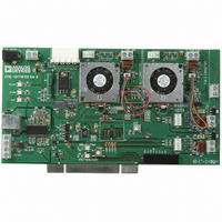
EVAL-ADT7467EB Analog Devices Inc, EVAL-ADT7467EB Datasheet - Page 44

EVAL-ADT7467EB
Manufacturer Part Number
EVAL-ADT7467EB
Description
BOARD EVALUATION FOR ADT7467
Manufacturer
Analog Devices Inc
Series
dBCool®r
Datasheet
1.EVAL-ADT7467EB.pdf
(80 pages)
Specifications of EVAL-ADT7467EB
Sensor Type
Temperature
Sensing Range
-40°C ~ 120°C
Interface
SMBus (2-Wire/I²C)
Sensitivity
±1.5°C
Voltage - Supply
3 V ~ 5.5 V
Embedded
No
Utilized Ic / Part
ADT7467
Lead Free Status / RoHS Status
Contains lead / RoHS non-compliant
ADT7467
Programming the PWM
The PWM
maximum PWM duty cycle for each output to be configured
from 0% to 100%. This allows the maximum PWM duty cycle
to be set in steps of 0.39%.
The value to be programmed into the PWM
Example 1: For a maximum PWM duty cycle of 50%,
Example 2: For a minimum PWM duty cycle of 75%,
PWM
Reg. 0x38, PWM1 maximum duty cycle = 0xFF (100% default)
Reg. 0x39, PWM2 maximum duty cycle = 0xFF (100% default)
Reg. 0x3A, PWM3 maximum duty cycle = 0xFF (100% default)
See the Fan Speed and PWM Duty Cycle section.
Figure 60. PWM
Value (decimal) = PWM
Value (decimal) – 50/0.39 = 128 (decimal)
Value = 128 (decimal) or 80 (hex)
Value (decimal) = 75/0.39 = 85 (decimal)
Value = 192 (decimal) or C0 (hex)
MAX
PWM
PWM
Registers
100%
MAX
MAX
MIN
0%
MAX
registers are 8-bit registers that allow the
Determines Maximum PWM Duty Cycle Below the THERM
T
MIN
Temperature Limit
MAX
MAX
Registers
/0.39
TEMPERATURE
MAX
register is given by
Rev. A | Page 44 of 80
STEP 6: T
T
control occurs once the programmed T
been exceeded. T
value, that is, a T
33%. If PWM
changes.
The T
procedure:
1.
2.
3.
4.
RANGE
Determine the maximum operating temperature for that
channel (for example, 70°C).
Through experimentation determine the fan speed (PWM
duty cycle value) that does not exceed the temperature at
the worst-case operating points. (For example, 70°C is
reached when the fans are running at 50% PWM duty
cycle.)
Determine the slope of the required control loop to meet
these requirements.
The ADT7467 evaluation software can graphically
program and visualize this functionality. Ask your local
Analog Devices sales representative for details.
RANGE
is the range of temperature over which automatic fan
PWM
100%
100%
50%
33%
0%
or fan control slope is determined by the following
RANGE
MIN
Figure 61. T
0%
MIN
Figure 62. Adjusting PWM
RANGE
is increased or decreased, the effective T
RANGE
FOR TEMPERATURE CHANNELS
T
RANGE
MIN
of 40°C holds true only for PWM
T
is a temperature slope, not an arbitrary
MIN
Parameter Affects Cooling Slope
30°C
40°C
T
RANGE
MIN
TEMPERATURE
Affects T
MIN
temperature has
RANGE
MIN
RANGE
=


